En-12
Cable tie (medium)
(accessories)
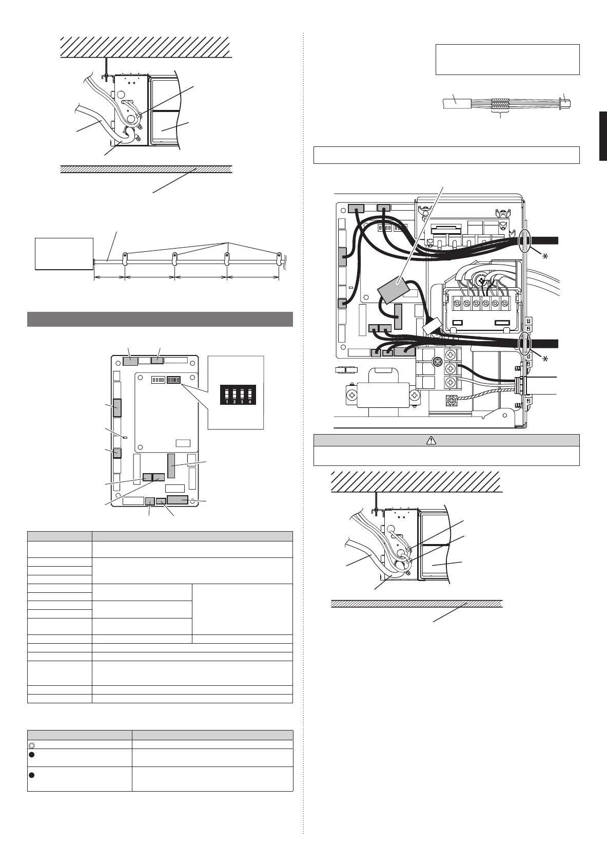
Avoid covering the air
inlet with the wiring.
Avoid touching the ceiling with the wiring
Ceiling
Conduit
(power supply
cable)
Do not bind the power supply cable and other cables together.
• Fix the conduit with the supporters as shown below.
Conduit (power supply cable)
Supporter
Indoor unit
30 in
(756 mm)
or less
54 in
(1,361 mm)
or less
54 in
(1,361 mm)
or less
54 in
(1,361 mm)
or less
6.5. Optional parts wiring
6.5.1. Layout of the indoor unit PCB
CN8
CN48
SW1
SW2
SW3
SW4
CNB01
4
Controller PCB
OFF ON
DIP switch
(SET 2)
Power indicator
lamp (green)
Name Application
Power indicator
lamp (green)
Indicates the state of the power supply. Refer to “Power indicator
lamp status” following.
CN150 Connect to the Grille. (*1)
CN151
CN152
CNA01 Apply voltage terminal For external input
CNA03
CNA02 Dry contact terminal
CNA04
DIP switch SET 2
(SW2)
Input signal type switching
CNB01 Output terminal For external output
CN8 For Remote sensor unit (*1)
CN48 For IR receiver unit (*1)
CN65 For one of the following.
• MODBUS® convertor (*1)
• Wireless LAN adapter (*1)
CN155 For Auto louver grille kit (*1)
CN820 For External power supply unit (*1)
*1: For details, refer to each installation manual.
6.5.2. Power indicator lamp status
Power indicator lamp (Green) Status contents
Lit
Lit when the power is turned on.
Fast flashing (every 0.1
second)
There is a fault with the communication board or the
main board.
Blinking (repeat 3 seconds ON
and 1 second OFF)
The indoor unit is turned off and power is supplied
from the External power supply unit (optional) to the
indoor unit PCB.
6.5.3. Connection methods
Wire modification for External
input/output wire
(1) Remove insulation from wire at-
tached to wire kit connector.
(2) Remove insulation from field
supplied cable. Use crimp type
insulated butt connector to join field
cable and wire kit wire.
(3) Connect the wire with connecting
wire with solder.
IMPORTANT:
Be sure to insulate the connection between the
wires.
Locally
purchased
Solder and insulate the connected parts.
Wire kit connector
(optional parts)
Wiring arrangement
In following figure, all the possible connectors are connected for description.
In actual installation, you cannot connect all the connectors at once.
EMI core (accessory
of the IR receiver unit)
*
CAUTION
To protect the cable insulation after opening a knockout hole, remove any burrs from the
edge of the hole.
Cable tie (medium/accessories)
Remote sensor, Auto Louver
grille, External power supply unit
Cable tie (medium/accessories)
External input and external
output, IR receiver unit
Avoid covering the air inlet
with the wiring.
Avoid touching the ceiling with the wiring
Ceiling
Power supply
cable
Do not bind the power supply cable and other cables together.
9374342556-02_IM.indb 12 27-Sep-19 10:30:12 AM

 Loading...