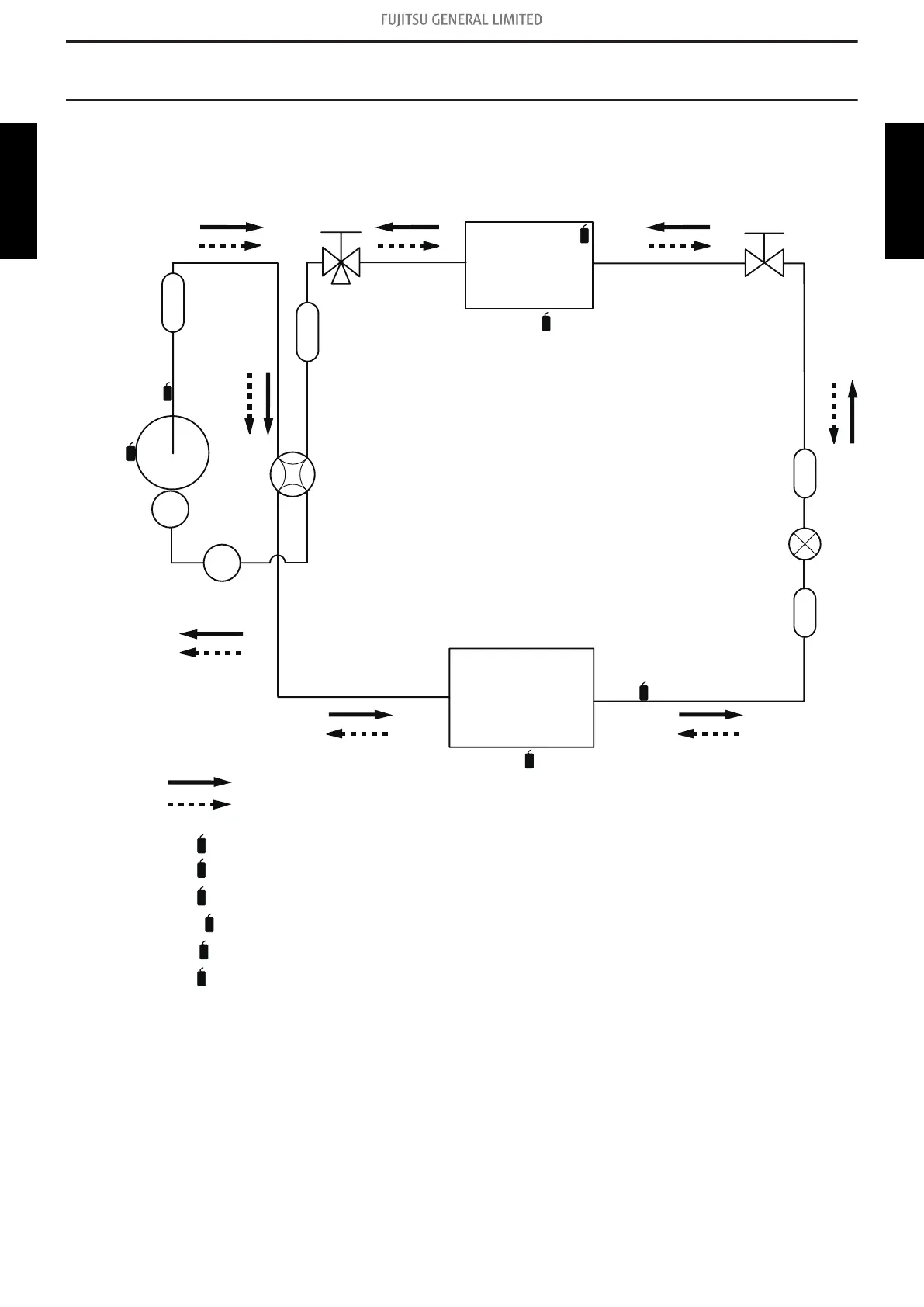
6. Refrigerant system diagrams
6-1. Models: AOUG09LZAS1, AOUG12LZAS1, and
AOUG15LZAS1
Strainer
Strainer
3-way
valve
2-way
valve
Muffler
4-way valve
Expansion valve
Heat exchanger
Heat exchanger
(INDOOR)
(OUTDOOR)
Compressor
Cooling
Heating
Th
D
Th
R
Th
O
Th
HO
Muffler
Accumulator
Th
PI
Th
C
: Thermistor (Discharge temperature)
: Thermistor (Outdoor temperature)
: Thermistor (Heat exchanger out temperature)
Th
D
: Thermistor (Compressor temperature)
Th
C
Th
O
Th
HO
: Thermistor (Pipe temperature)
Th
PI
: Thermistor (Room temperature)
Th
R
6-1. Models: AOUG09LZAS1, AOUG12LZAS1, and AOUG15LZAS1 - (02-13) - 6. Refrigerant system diagrams
TECHNICAL DATA
AND PARTS LIST
TECHNICAL DATA
AND PARTS LIST
 Loading...

