8. Function settings
To adjust the functions of this product according to the installation environment, various types of
function settings are available.
NOTE:
Incorrect settings can cause a product malfunction.
8-1. Outdoor unit
¢
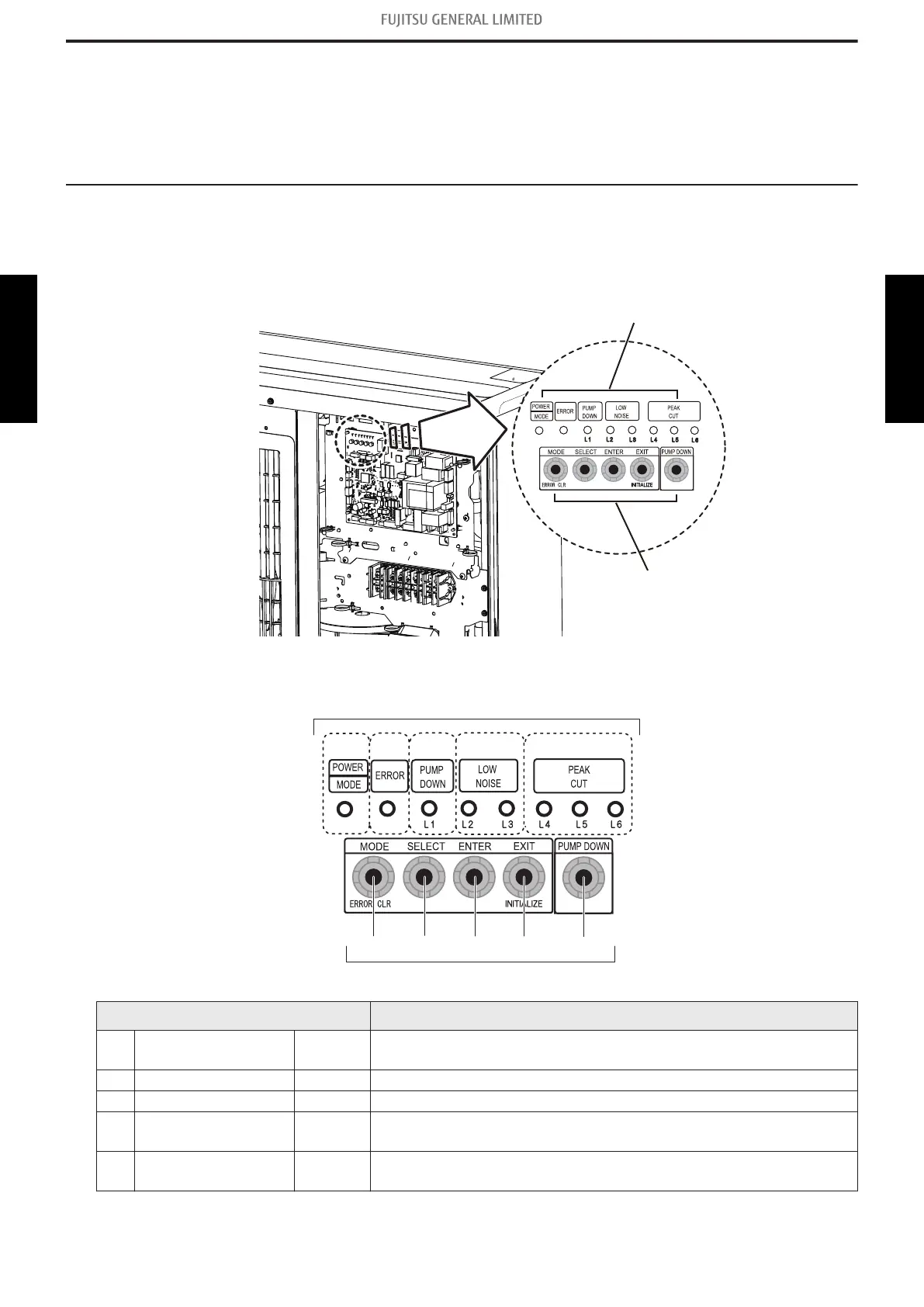
Control PCB and switch buttons location
Control PCB of the outdoor unit is located as shown in the following figure.
Switch buttons and the functions
S134
S133
S132 S131 S130
(1) (2) (3) (4) (5)
LED lamps
Switch buttons
LED lamp Function or operation method
(1) POWER/MODE Green
Lights on while power on.
Local setting in outdoor unit or error code is displayed with blink.
(2) ERROR Red Blinks during error operation.
(3) PUMP DOWN (L1) Orange Lights on during pump down operation.
(4)
LOW NOISE MODE
(L2 and L3)
Orange
Lights on during “Low noise mode” when local setting is activated.
(Lighting pattern of L2 and L3 indicates low noise level.)
(5)
PEAK CUT MODE
(L4, L5, and L6)
Orange
Lights on during “Peak cut mode” when local setting is activated.
(Lighting pattern of L4, L5, and L6 indicates peak cut level.)
- 157 -
8-1. Outdoor unit 8. Function settings
SYSTEM
DESIGN
SYSTEM
DESIGN
 Loading...