En-11
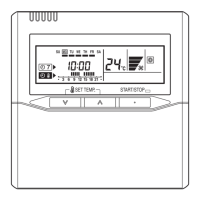
If no buttons are pressed within 30 seconds after the signal code is displayed, the sys-
tem returns to the original clock display. In this case, start again from step 1.
The air conditioner signal code is set to A prior to shipment.
Contact your retailer to change the signal code.
The remote controller resets to signal code A when the batteries in the remote controller
are replaced. If you use a signal code other than signal code A, reset the signal code
after replacing the batteries.
If you do not know the air conditioner signal code setting, try each of the signal codes
( ) until you fi nd the code which operates the air conditioner.
9.4. Special installation methods
This possible only the wired remote controller (Option)
CAUTION
When setting DIP switches, do not touch any other parts on the circuit board directly
with your bare hands.
Be sure to turn off the main power.
9.4.1. Simultaneous multi-system operation
By combining with an outdoor unit, 2 units for twin and 3 units for triple indoor units, can •
be switched ON/OFF simultaneously.
Wiring method(1)
Refer to 6.ELECTRICAL WIRING for wiring procedure and wiring method.•
The indoor unit is connected the outdoor unit using a transmission cable is “primary”.•
Connect the remote controller wire to the primary unit.•
Twin type ( 18, 22, 24 type only )
Outdoor
unit
Indoor
unit
1
Indoor
unit
2
Remote
controller
[primary]
[secondary]
Triple type ( 18type only )
Outdoor
unit
Remote
controller
: Transmission cable, Power supply cable : Power supply cable
: Bus wire: Remote controller cable
Indoor
unit
1
[primary]
Indoor
unit
2
[secondary]
Indoor
unit
3
[secondary]
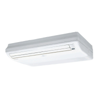
Set the R.C. address (DIP switch setting )(2)
Set the R.C. address of each indoor unit using the DIP switches on the indoor unit
circuit board. (See the following table and fi gure.)
The DIP switches are normally set to make the R.C. address 00.
Indoor unit R.C. address DIP SWITCH No.
1234
1
00 OFF OFF OFF OFF
2
01 ON OFF OFF OFF
3
02 OFF ON OFF OFF
DIP switches
Example :
R.C. address 02
ON
Circuit board in the control box of indoor unit.
NOTE
Be sure to set the R.C. address sequentially.
Set the primary and secondary (Remote controller setting)(3)
Turn on all of the indoor units.1.
Set the “primary” and “secondary” settings.2.
(Set the indoor unit that is connected to the outdoor unit using a transmission cable
as the “primary”.)
Function Number
Setting Value
Primary
51
00
Secondary 01
After completing the function settings, turn off all of the indoor units, and then turn 3.
them back on.
If error code 21, 22, 24 or 27 is displayed, there may be an incorrect setting. *
Perform the remote controller setting again.
Twin type ( 18, 22, 24 type only )
00 01
00 01
R.C. address
Primary/Secondary setting
(DIP switch setting)
(Function number 51)
Out door
unit
Remote
controller
Indoor
unit
1
[primary]
Indoor
unit
2
[secondary]
Triple type ( 18type only )
00 01 02
00 01 01
R.C. address
Primary/Secondary setting
(DIP switch setting)
(Function number 51)
Out door
unit
Remote
controller
: Transmission cable, Power supply cable : Power supply cable
: Bus wire: Remote controller cable
Indoor
unit
1
[primary]
Indoor
unit
2
[secondary]
Indoor
unit
3
[secondary]
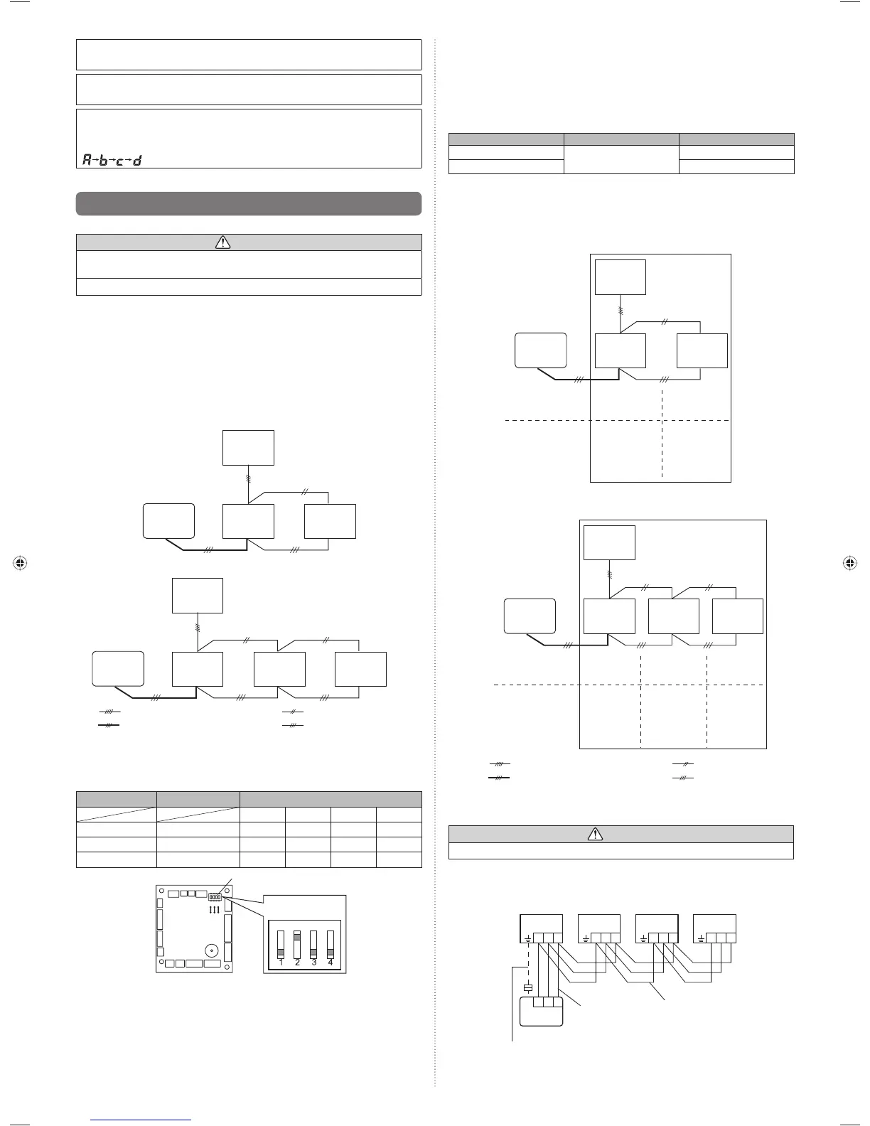
9.4.2. Group control system
CAUTION
Group control cannot be used when using it by the fl exible multi type.
A number of indoor units can be operated at the same time using a single remote controller.
(1) Wiring method (indoor unit to remote controller)
123
123
123 123 123
Indoor
unit 1
Bus wire
Remote
controller cable
Remote controller
When ground wire is necessary
Indoor
unit 2
Indoor
unit 3
Indoor
unit 4
9374318445-05_IM.indb 11 4/6/2012 10:08:19 AM
 Loading...