En-8
CAUTION
Tighten the indoor unit
connection cable and power supply indoor and outdoor unit,
branch box terminal board connections fi rmly with the terminal board screws. Faulty
connection may cause a
fi re.
If the indoor unit connection cable and power supply are wired incorrectly, the air condi-
tioner may be damaged.
Connect the indoor unit connection cable by matching the numbers of the outdoor,
branch box and indoor units terminal board numbers as shown in terminal label.
Earth both the indoor and outdoor, branch box units by attaching a earth cable.
Unit shall be grounded in compliance with the applicable local and national cables.
CAUTION
Be sure to refer to the above diagram for do correct fi eld wiring. Wrong wiring causes mal-
function of the unit.
Check local electrical rules and also any specifi c wiring instructions or limitation.
6.2. Connection cable preparation
Keep the earth wire longer than the other wires.
Power supply cable
or connection cable
20 mm
50mm or more
Earth wire
• Use a 4-core wire cable.
6.3. Connection of wiring
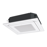
(1) Remove the 4 topping screws.
Electric component
box
Electric component box
RFM
CAUTION
Do not remove the screws. If the stays are removed, the electric component box will
fall.
If you use as “Floor console”, you must remove screws and RFMs (2 positions).
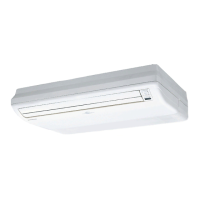
(2) Pull out the electric component box.
Electric component box
Wires
Clamp
Remove the
clamp.
Install the
clamp.
When removing the electric component box, remove the clamp from the cables.•
After completing the work, fasten the cables as they were originally by installing the •
clamp.
Remove the electric component box cover.(3)
Base
Electric component cover box
Remove the 3 tapping screws.
CAUTION
Be careful not to pinch the lead wires between the electric component box and base.
(4) After wiring is complete, secure the remote controller cable, connection cable with the
cable-tie.
Cable-tie (accessory)
Remove excess after
installing
Wired remote con-
troller cable (option)
Transmission cable
Install the electrical component box in the original position after securing the cover.(5)
Install the connection cable with the supplied wire clamper.(6)
Transmission cable
Wire clamper (accessory)
Remove excess after
installing
CAUTION
Do not bundle the remote controller cable, or wire the remote controller cable in paral-
lel, with the indoor unit connection wire (to the outdoor unit) and the power supply
cable. It may cause erroneous operation.
6.4.
Floor/ceiling select switch
This unit was set for use as a ceiling type at the factory.(1)
When using the unit as a fl oor type, perform the following settings in FUNCTION SET-(2)
TING. (Refer to 9. FUNCTION SETTING.)
Setting the Cooler Room Temperature Correction
→ Setting Value “01”
Setting the Heater Room Temperature Correction
→ Setting Value “01”
7. MOUNT THE COVER PLATE AND THE INTAKE
GRILLE
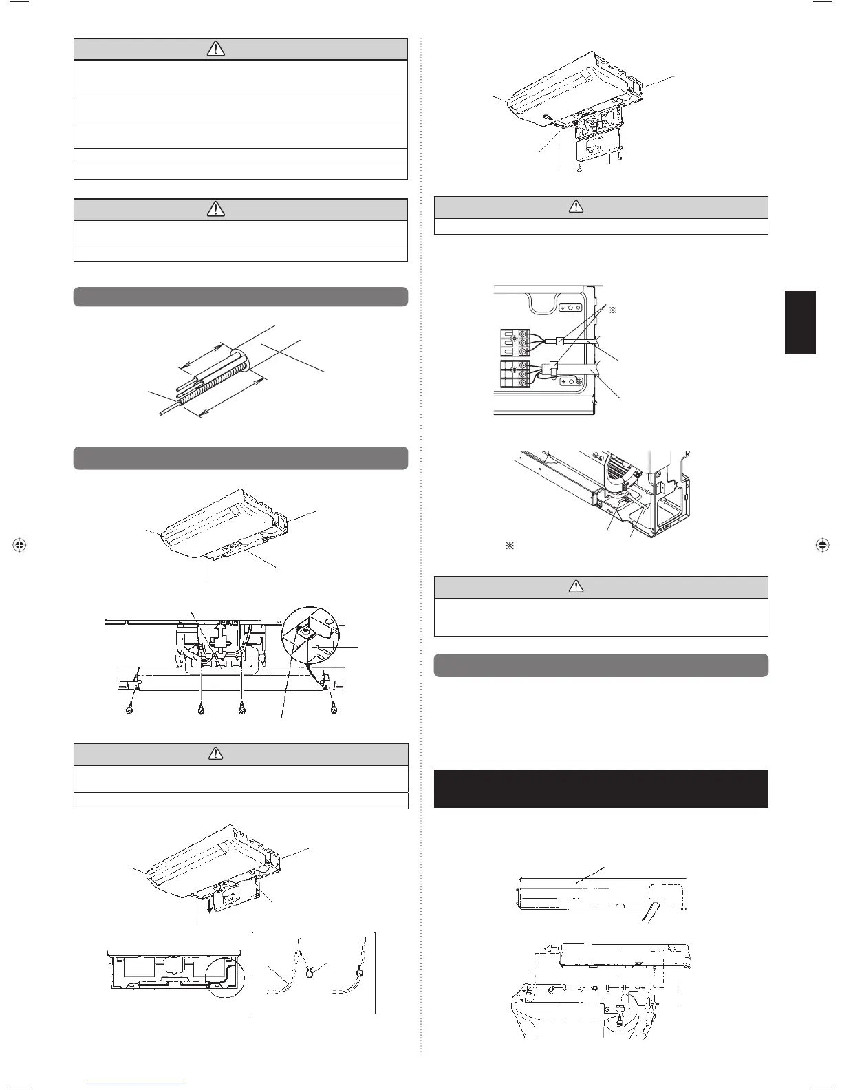
1. Mount the cover plate (right)
Cut a pipe exit hole in the right plate. This is only when the pipe exits from the right (1)
side. (This operation is not required when the protrusion is on the top or rear.)
Cover plate (Right)
Join the cover plates (right) and mount with the screw (ø4 × 10).(2)
9374318445-05_IM.indb 8 4/6/2012 10:08:17 AM
 Loading...