En-12
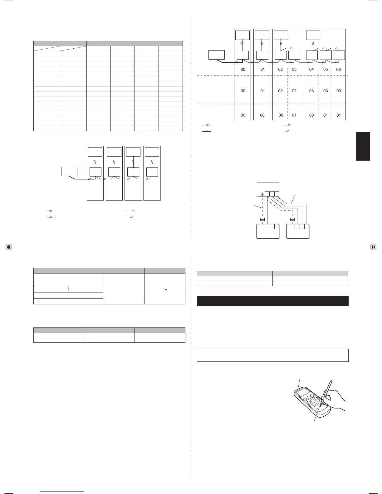
Set the R.C. address (DIP switch setting) (2)
Set the R.C. address of each indoor unit using the DIP switches on the indoor unit
circuit board. (See the following table and fi gure.)
The DIP switches are normally set to make the R.C. address 00.
Indoor unit
R.C. address
DIP SWITCH No.
1234
①
00 OFF OFF OFF OFF
②
01 ON OFF OFF OFF
③
02 OFF ON OFF OFF
④
03 ON ON OFF OFF
⑤
04 OFF OFF ON OFF
⑥
05 ON OFF ON OFF
⑦
06 OFF ON ON OFF
⑧
07 ON ON ON OFF
⑨
08 OFF OFF OFF ON
⑩
09 ON OFF OFF ON
⑪
10 OFF ON OFF ON
⑫
11 ON ON OFF ON
⑬
12 OFF OFF ON ON
⑭
13 ON OFF ON ON
⑮
14 OFF ON ON ON
⑯
15 ON ON ON ON
NOTE
Be sure to set the R.C. address sequentially.
00 01 02 03
R.C. address
(DIP switch setting)
Remote
controller
: Transmission cable, Power supply cable : Power supply cable
: Bus wire: Remote controller cable
Outdoor
unit
1
Indoor
unit
1
Indoor
unit
2
Indoor
unit
3
Indoor
unit
4
Outdoor
unit
2
Outdoor
unit
3
Outdoor
unit
4
¡Settings when simultaneous Multi is included
Set the refrigerant circuit address (Remote controller setting)(3)
Turn on all of the indoor units.1.
* Turn on the indoor unit with the R.C. address 00 last.
(Within 1 minute)
Set the refrigerant circuit address.2.
Assign the same number to all of the indoor units connected to an outdoor unit.
(The unit is factory-set to “00”)
Refrigerant circuit address
Function Number Setting Value
00
02
00
〜
15
01
〜
14
15
Set the “primary” and “secondary” settings. (Remote controller setting)(4)
(Set the indoor unit that is connected to the outdoor unit using a transmission cable as the
“primary”.)
Function Number
Setting Value
Primary
51
00
Secondary 01
After completing the function settings, turn off all of the indoor units,
and then turn them back on.
* If error code 21, 22, 24, or 27 is displayed, there may be an incorrect
setting. Perform the remote controller setting again.
NOTE
When different indoor unit models are connected using the group control system, some •
functions may no longer be available.
If the group control system contains multiple units that are operated simultaneously, con-•
nect and set the units as shown below.
Auto-changeover operates under the same mode with model R.C. address 00.•
It should not be connected to any other Gr that is not of the same series (A**G only).•
R.C. address
Standard
pair
Standard
pair
Simultaneous
twin
Simultaneous
triple
Refrigerant circuit
address setting
Primary/Secondary setting
(DIP switch setting)
(Function number 02)
(Function number 51)
Remote
controller
: Transmission cable, Power supply cable : Power supply cable
: Bus wire: Remote controller cable
Outdoor
unit
1
Outdoor
unit
2
Outdoor
unit
3
Outdoor
unit
4
Indoor
unit
1
Indoor
unit
2
Indoor
unit
3
Indoor
unit
4
Indoor
unit
5
Indoor
unit
6
Indoor
unit
7
9.4.3. Dual remote controllers
2 separate remote controllers can be used to operate the indoor units.•
The timer and self-diagnosis functions cannot be used on the secondary unit of remote •
controller.
Wiring method (indoor unit to remote controller)(1)
1 231 23
1 2 3
Indoor unit
Secondary
unit
Primary unit
Remote controller cable
Remote
controller
Remote
controller
When ground wire
is necessary
Remote controller DIP switch 1 setting (2)
Set the remote controller DIP switch 1-No. 2 according to the following table.
DIP SW 1-No. 2
Primary unit OFF
Secondary unit ON
10. TEST RUN
CHECK ITEMS
Is operation of each button on the remote controller normal?(1)
Does each lamp light normally?(2)
Do not air fl ow direction louvers operate normally?(3)
Is the drain normal?(4)
Is there any error noise and vibration during operation?(5)
Do not operate the air conditioner in the running state for a long time.•
Test running•
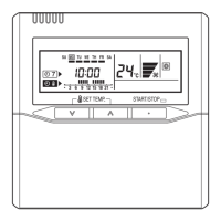
When the air conditioner is run by pressing the remote controller test run button, the
OPERATION and TIMER Lamps fl ash slowly at the same time.
[Operation method]
For the operation method, refer to the operating •
manual.
The outdoor unit may not operate depending on the •
room temperature. In this case, press the TEST RUN
button on the remote controller while the air condi-
tioner is running. (Point the transmitter section of
the remote controller toward the air conditioner and
press the TEST RUN button with the tip of a ballpoint
pen, etc.)
To end test operation, press the remote controller •
START/STOP button. (When the air conditioner
is running by pressing the TEST RUN button, the
OPERATION Lamp and TIMER Lamp will simultane-
ously fl ash slowly.)
Transmitter section
TEST RUN button
9374318445-05_IM.indb 12 4/6/2012 10:08:20 AM
 Loading...