20 – English Mainboard D3488
58 Fujitsu
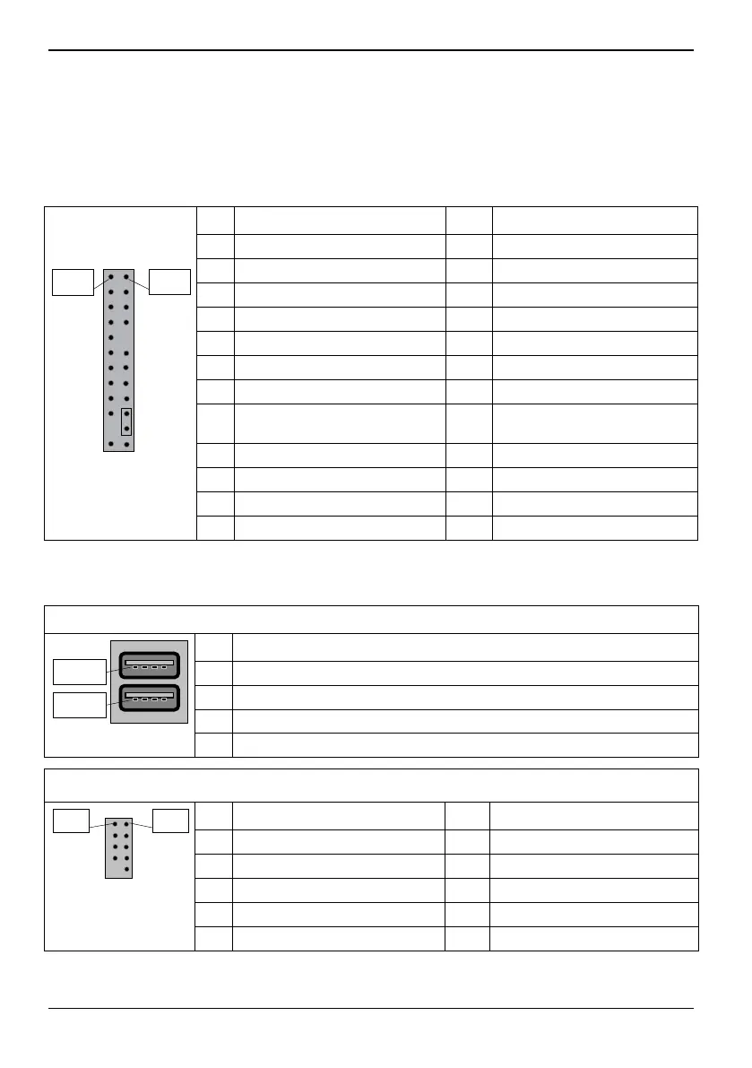
Front panel pin connector (internal)
Normally, a chassis has some control or signal wires can be connected onto a motherboard for hard
drive LED, Power LED, power button, and reset button; The front panel connector has been
implemented on D3488 for such purposes.
PIN Signal PIN Signal
1 HD-LED + 2 Power LED +
3 HD-LED - 4 Power LED -
5 GND 6 Power Button
7 RST L 8 GND
9 Chassis Detect WS L 10 Key
11 Chassis Detect Baku L 12 GND
13 LED1 + (for USB Security) 14 LED1 -
15 Power Button (only S5, does
not work in low power S5)
16 Power Button (only S5, does
not work in low power S5)
17 Speaker + 18 Password Skip
19 GND 20 GND (0,1K)
21 Key 22 GND (0,1K)
Pin 2
Pin 1
23 Speaker - 24 Recover BIOS
Communication connectors
USB 2.0 port (external)
PIN Signal
1 VCC AUX (safe mode)
2 Data negative
3 Data positive
Pin 1
Pin 1
4 GND
USB 2.0 port (internal) – Internal/Front
PIN Signal PIN Signal
1 VCC AUX 2 VCC AUX
3 Data negative Port X 4 Data negative Port Y
5 Data positive Port X 6 Data positive Port Y
7 GND 8 GND
Pin 1 Pin 2
9 Key 10 NC
 Loading...