11
3. INSTALLATION
3.1 Equipment List
3.2 Installation Considerations
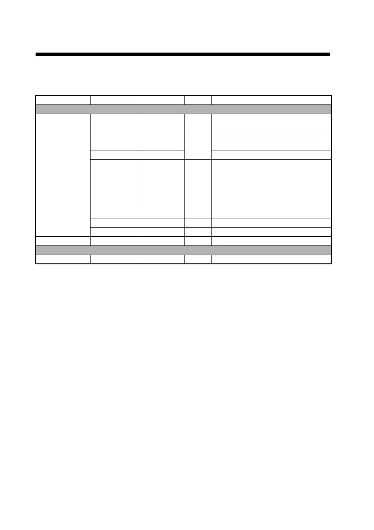
Name Type Code No. Qty Remarks
Standard supply
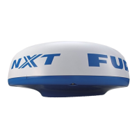
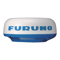
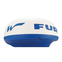
Radar Sensor RSB-126-103 - 1
Installation
Materials
CP03-35800 000-024-974 Select
one
Power cable assy., 10 m
CP03-35810 000-024-975 Power cable assy., 15 m
CP03-35820 000-024-976 Power cable assy., 20 m
CP03-35830 000-024-977 Power cable assy., 30 m
CP03-35701 001-265-920 1 - Hex bolt*(M10×25), 4 pcs.
- Flat washer (M10 SUS304), 4 pcs.
- Spring washer (M10 SUS304), 4 pcs.
*For use if thickness of platform is
6–10 mm.
Documents OME-36360 - 1 Operator’s Manual
MDC-36360 - 1 C-ROHS list
E32-01314 - 1 Template
E32-01401 - 1 SSID, password information
Spare Parts SP03-17801 001-265-910 1 5A fuse, 2 pcs.
Optional supply
Radome Mount OP03-209 001-078-350 1 Mast mounting bracket for sailboat
General considerations:
• Do not apply paint, anti-corrosive sealant or contact spray to coating or plastic parts. Those items
contain solvents that can damage coating and plastic parts.
• The radar sensor has no power switch. Therefore, it is recommended that you connect the sensor
to a disconnecting device (circuit breaker, etc.) to control the power.
Sensor placement:
• The radar sensor uses the 2.4 GHz wireless LAN radio band to forward radar echoes to the iOS
terminal. Separate the sensor well away from products which also use this band (microwave
range, Bluetooth devices, etc.) to prevent mutual interference.
• Install the radar sensor on the hardtop, radar arch or on a mast on an appropriate platform. (For
sailboats, a “radome mount” is optionally available for fixing the sensor to a mast.) Place the sen-
sor where there is a good all-round view with, as far as possible, no part of the ship’s superstruc-
ture or rigging intercepting the scanning beam. Any obstruction will cause shadow and blind
sectors. Be sure there are no metallic objects near the antenna. See the next page for typical
placement on a sailboat and powerboat.
• Observe the wireless LAN communication range noted in the illustration on the next page.
• In order to reduce the chance of picking up electrical interference, avoid where possible routing
the power cable near other electrical equipment onboard. Also, avoid running the cable in parallel
with other power cables.
• Select a location that does not allow water to accumulate at the base of the sensor.
• A magnetic compass will be affected if the radar sensor is too close to the compass. Observe the
compass safe distances mentioned on page ii to prevent interference to a magnetic compass.
 Loading...