 Loading...


Do you have a question about the Furuno FS-2570 and is the answer not in the manual?
Step-by-step guide for checking the installation of the system components, including mounting, wiring, and antennas.
Basic check on understanding the overall system configuration.
Checks for proper mounting and wiring of main system units like transceiver, controller, and power supply.
Checks for correct installation and safety of the MF/HF antenna, including lead-in wire and insulator.
Verifies correct grounding, antenna wire security, and coaxial cable shielding of the antenna coupler.
Checks grounding and waterproofing of the RX antenna.
Confirms NBDP terminal connection and installation of the optional NBDP DSP board.
Checks connections and jumper settings on the W/R2 board and TX FIL board.
Verifies that identification information is marked on units with labels.
Checks the power supply unit for correct specifications and internal wiring.
Verifies system settings including DIP switches, MMSI registration, and model selection.
Checks the setting of JP-3 on the W/R board, related to antenna unit power.
Verifies DIP switch settings on the T-CPU board for GNSS, indicator, and alert button connections.
Confirms the registered MMSI within the DSC setup display.
Checks if the correct model (FS-1570 or FS-2570) is selected and verifies RT self-test data.
Verifies RT setup, including TX frequency settings according to local regulations.
Confirms SYSTEM settings in DSC setup, including WATCH RCVR for sea area A3.
Checks NBDP terminal setup, AAB/ID registration, and Slave Delay setting.
Details the function and default settings of DIP switches on the T-CPU board.
Shows the default settings for various items in the DSC System Setup menu.
Lists the default settings for the RT System setup menu.
Provides the default settings for NBDP terminal setup menus (IB-581/583).
Outlines procedures for self-tests on DSC, RT, terminal units, antenna coupler, and printer.
Instructions on how to check the system's program version.
Lists program versions for various system components.
Describes functional checks for position display, antenna tuning, power, receiver sensitivity, scanning, and printing.
A checklist for verifying transmitter performance across different frequencies.
Instructions for performing communication tests via Telephone, DSC, and NBDP.
Provides checks for noise and interference during transmission and reception.
A table to record interference checks from the FS-1570/2570 system with other equipment.
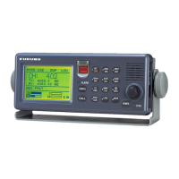
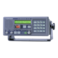
Basic overview of the FS-1570/2570 MF/HF radiotelephone with built-in DSC and NBDP.
Shows the system configuration for FS-1570 (150W) and FS-2570 (250W) models.
Details how to connect the NBDP terminal IB-581 to the system.
Lists signal types and remarks for each port on the units.
Explains the use of handset ports and hook signals.
DSC distress alert has the highest priority over other functions.
Describes how received DSC messages are displayed based on priority.
Explains the optional PSM-01 unit for monitoring ship's power supply status.
Provides notes on using the NBDP terminal and adjusting its brightness.
Details front/rear views of FS-2570C display unit and its internal boards.
Shows front, side, and bottom views of the FS-2570T transceiver unit.
Shows front, side, and bottom views of the FS-1570T transceiver unit.
Lists and describes various boards within the transceiver unit.
Shows internal views and components of the AT-1560 antenna coupler.
Details front, rear views, and dimensions of the IB-583 terminal unit.
Shows the HS-2001 handset and its internal components.
Explains how to register MMSI, model, and group ID for the system.
Details the setup procedures for the RT (Radio Telephone) system.
Guides through the setup process for the DSC (Digital Selective Calling) system.
Explains the function and default settings of DIP switches on the T-CPU board.
Describes jumper settings for FAX-5 and TR antenna usage.
Instructions for installing the DSP board for NBDP communication.
Details the necessary settings for the NBDP terminal IB-581/583.
Overview of programs used by the radiotelephone and updating methods.
Explains PC connections for program updating on C-CPU, T-CPU, and NBDP terminals.
Specifies DIP switch settings on the T-CPU board for program updates.
Detailed steps for updating programs on T-CPU, C-CPU, DSC, NBDP, IB-581, and IB-583.
Lists the contents of program files for various components like C-CPU, T-CPU, and modems.
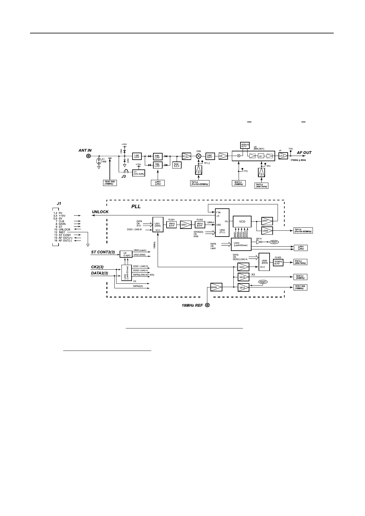
Shows block diagrams of the transceiver units for FS-1570T and FS-2570T.
Describes the power supply unit, including protectors and regulator boards.
Details CPUs, memory, signals, interface circuits, and DSP on the T-CPU board.
Explains block diagram, local oscillator, and transmitter/receiver circuits of the TX/RX board.
Describes PA boards for FS-1570T/FS-2570T, including bias adjustments and characteristics.
Details the DSC receiver board, its specifications, and functions.
Explains the block diagram and components of the C-CPU and C-IF boards.
Describes the AT-1560 antenna coupler, its boards, and timing of control signals.
Details the IB-583 NBDP terminal, its major functions, and board descriptions.
Describes DSC and RT self-tests, including program version checking.
Explains the self-test procedure for the AT-1560 antenna coupler.
Details the self-test procedure for IB-581 and IB-583 terminal units.
Describes tone tests for character transmission and mark/space tone measurement.
Guides on unlocking and performing factory tests for various PCB functions.
Lists and explains messages that appear on the control unit and NBDP terminal.
Provides instructions for changing the backup battery on the IB-583 TERM CPU board.
Details power data settings, output power measurement, and adjustment procedures.
Explains TX operating frequency measurement and tone frequency adjustment.
Describes PA bias adjustment procedures for different boards and transistor specifications.
Explains TX gain adjustment using potentiometers and proper microphone gain.
Details receiver gain checking and adjustment procedures.
Procedure for transmitting and acknowledging DSC test calls with a coast station.
Guide to receiving Maritime Safety Information and making ARQ communication.
Steps to cancel a false distress alert and broadcast the cancellation.
Actions for ships upon reception of DSC distress alerts.
General specifications including communication system, emission class, frequency range, and display.
Transmitter specifications detailing frequency range, output power, modulation, and AF input.
Receiver specifications including receiving system, frequency range, and sensitivity.
Specifications for Digital Selective Calling and Watch Keeping Receiver functions.
Specifications for the optional General Watch Keeping Receiver on FS-2570.
General specifications for the optional NBDP function.
Specifications for the IB-583 Terminal Unit including display, CPU, memory, and keyboard.
Specifications for the AT-1560 antenna coupler including tuning system, frequency range, and power capability.
Details input data sentences like Ship's Position and Time.
Specifies power requirements for transceiver units and optional AC/DC power supply.
Details ambient temperature, humidity, waterproofing, and vibration specifications.
Specifies the coating colors for the control unit, transceiver unit, and antenna coupler.
Schematic diagram for the 150W SSB interconnection.
Schematic diagram for the 250W SSB interconnection.
Schematic diagrams for FS-1570T and FS-2570T transceiver units.
Schematic diagrams for the Control Unit (FS-2570C).
Schematic diagram for the Handset unit (HS-2001).
Schematic diagrams for the Antenna Coupler unit (AT-1560).
Schematic diagrams for the NBDP Terminal Unit (IB-581/583).
Schematic diagrams of the AC/DC Power Supply Units.
Schematic diagram of the Power Status Monitor.
Schematic diagrams for the Printer Interface Unit.
Schematic diagram for the Pre Amplifier Unit.