• If you are installing the stereo in a location that is exposed
to water, apply silicone-based marine sealant on the
mounting surface around the cutout.
NOTICE
Do not install the included mounting gasket if you applied
sealant to the mounting surface. Using sealant and the
mounting gasket may reduce water resistance.
13
Place the stereo into the cutout.
14
Secure the stereo to the mounting surface using the included
screws .
You should hand-tighten the screws when securing the
stereo to the mounting surface to avoid overtightening them.
15
Snap the screw covers in place .
Connection Considerations
For the stereo to function correctly, you must connect it to
power, to speakers, and to input sources. You should carefully
plan the layout of the stereo, speakers, input sources, optional
NMEA 2000
®
network, and optional FUSION PartyBus
™
devices
or network before making any connections.
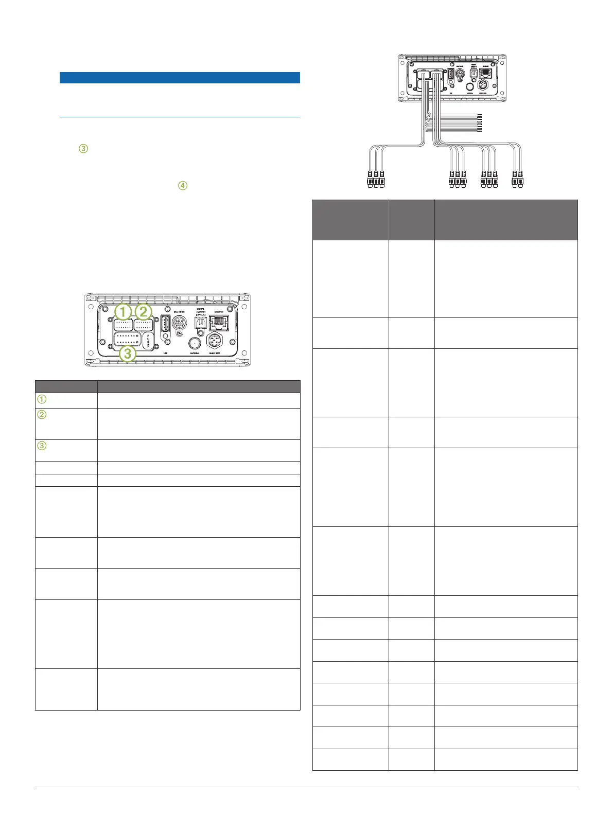
Port Identification
Item Description
Connects the stereo to the wiring harness for zone 3.
Connects the stereo to the wiring harness for auxiliary
input 1, and for the line and subwoofer outputs for
zones 1 and 2.
Connects the stereo to the power and speaker wiring
harness.
FUSE Contains the 15 A fuse for the device.
USB Connects the stereo to a USB source.
SXM TUNER Connects the stereo to a SiriusXM
®
Connect Tuner to
receive SiriusXM stations where available (not
included).
Connects to a FUSION DAB module to receive DAB
stations where available (not included).
DIGITAL
AUDIO IN
(OPTICAL)
Connects the stereo to an optical digital audio source,
such as TV or DVD player.
ETHERNET Connects the stereo to another FUSION PartyBus
stereo, zone stereo, or network (FUSION PartyBus
Networking, page 4).
ANTENNA Connects the stereo to a typical AM/FM antenna.
If you are installing the stereo on a boat with a metal
hull, you must use a ground-dependent antenna. If
you are installing the stereo on a boat with a non-
metal hull, you must use a ground-independent
antenna. See the installation instructions provided
with your antenna for more information.
NMEA 2000 Connects the stereo to a NMEA 2000 network (NMEA
2000 System Wiring Diagram, page 4).
Connects to an NRX series remote control directly
(Configuring an Optional Wired Remote, page 4).
Wiring Harness Wire and Connector Identification
Wire or RCA
Connector
Function
Bare Wire
Color or
RCA Label
Name
Notes
Ground (-) Black Connects to the negative terminal of
a 12 Vdc power source capable of
supplying 15 A. You should connect
this wire before connecting the yellow
wire. All accessories connected to the
stereo must share a common ground
location (Connecting to Power,
page 3).
Power (+) Yellow Connects to the positive terminal of a
12 Vdc power source capable of
supplying 15 A.
Ignition Red Connects to a separately-switched,
12 Vdc connection, such as an
ignition bus, to turn the stereo on and
off. If you are not using a switched
12 Vdc connection, you must connect
this to the same source as the yellow
(power) wire
Amplifier on Blue Connects to optional external
amplifiers, enabling them to turn on
when the stereo turns on.
Telemute Brown Activates when connected to ground.
For example, when you connect this
wire to a compatible, hands-free
mobile kit, the audio mutes or the
input switches to AUX when a call is
received and the kit connects this
wire to ground. You can enable this
functionality from the settings menu.
Dim Orange Connects to the boat's illumination
wire to dim the stereo screen when
the lights are on.
The gauge of the illumination wire
must be suitable for the fuse
supplying the circuit it is connected
to.
Speaker zone 1
left (+)
White
Speaker zone 1
left (-)
White/
black
Speaker zone 1
right (+)
Gray
Speaker zone 1
right (-)
Gray/black
Speaker zone 2
left (+)
Green
Speaker zone 2
left (-)
Green/
black
Speaker zone 2
right (+)
Purple
Speaker zone 2
right (-)
Purple/
black
2 Apollo MS-RA670 Installation Instructions
 Loading...