P
P
G
G
-
-
6
6
0
0
0
0
0
0
T
T
h
h
r
r
e
e
a
a
d
d
D
D
i
i
a
a
m
m
e
e
t
t
e
e
r
r
G
G
a
a
g
g
e
e
O
O
p
p
e
e
r
r
a
a
t
t
i
i
o
o
n
n
M
M
a
a
n
n
u
u
a
a
l
l
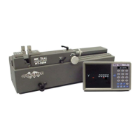
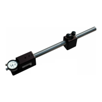
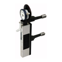
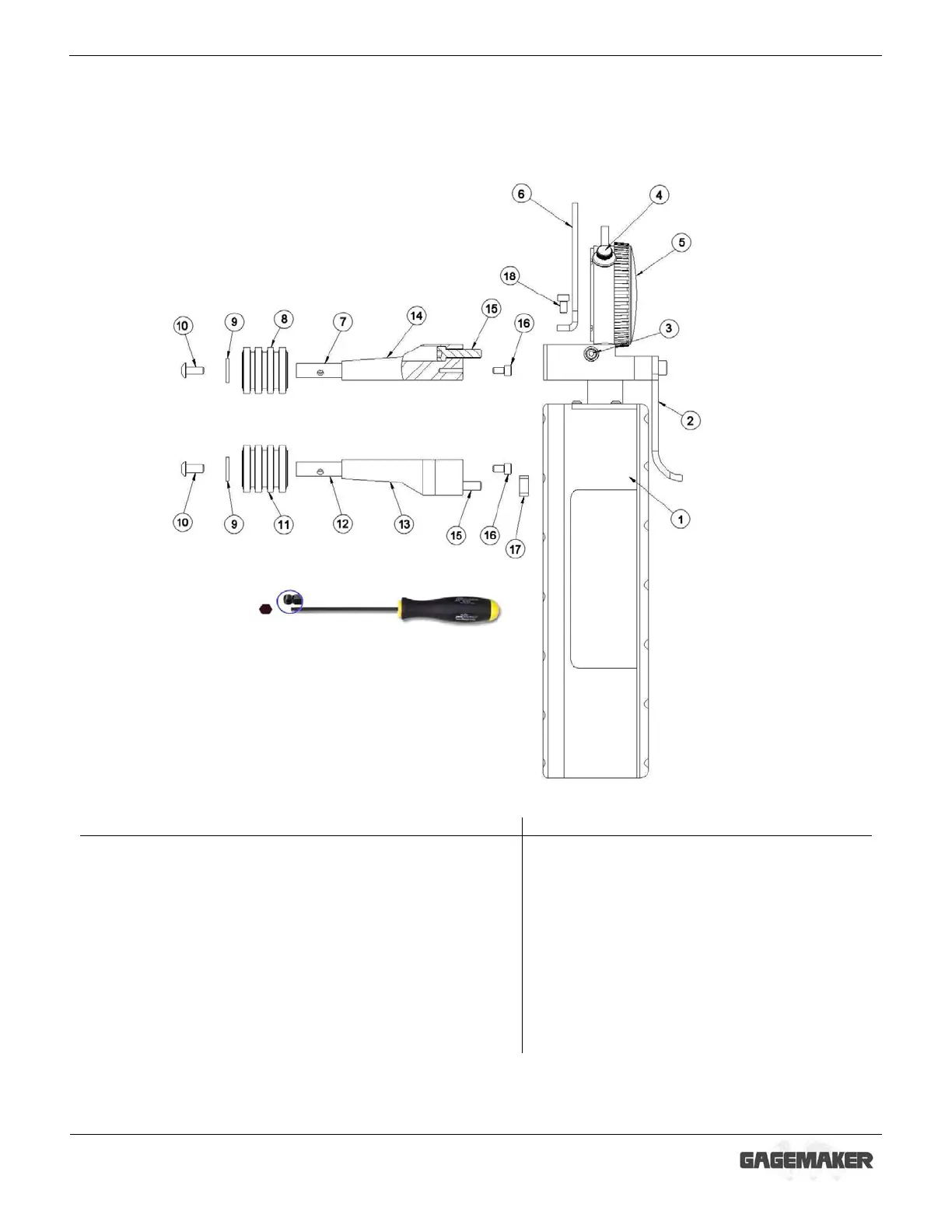
System Components
Take some time to become familiar with all the parts that make up the PG-6000 gage by
reviewing the labeled diagram below. The part names are important for understanding the
operating instructions.
Component List
1
Gage body 1 10 #10-32 X ¼” button head lock screw 2
2
Retraction lever 1 11 Lower thread roll 1
3
Indicator binder nut 1 12 Lower thread roll pin 1
4
Indicator clamp 1 13 Lower arm 1
5
Indicator 1 14 Upper arm 1
6
Indicator protector 1 15 Lock screw 2
7
Upper thread roll pin 1 16 Socket head cap screw 2
8
Upper thread roll 1 17 Key 1
9
# 10 washer 2 18 Indicator guard hold down screw 1
 Loading...