• The alarm can be mounted under the dashboard.
• If needed, the alarm wires can be extended with 28 AWG
(0.08 mm
2
) wire.
NMEA 2000
®
Connection Considerations
• The CCU and the helm control must connect to a NMEA
2000 network.
• If your boat does not already have a NMEA 2000 network,
one can be built using the included NMEA 2000 cables and
connectors (page 12).
• To use the advanced features of the autopilot, optional
NMEA 2000-compatible devices, such as a wind sensor, a
water-speed sensor, or a GPS device, can be connected to
the NMEA 2000 network.
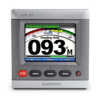
Helm Control Mounting Considerations
• The mounting location should provide optimal viewing as you
operate your vessel.
• The mounting location should allow easy access to the keys
on the helm control.
• The mounting surface must be strong enough to support the
weight of the helm control and protect it from excessive
vibration or shock.
• The area behind the mounting surface must allow room for
the routing and connection of the cables.
• There should be at least a 3 in. (8 cm) clearance behind the
case of the helm control.
• The mounting location must be at least 9½ in. (241 mm) from
a magnetic compass, to avoid interference.
• The mounting location must be in an area that is not exposed
to extreme temperature conditions (page 18).
Helm Control Connection Considerations
• The helm control must connect to the NMEA 2000 network.
• Optional NMEA
®
0183-compatible devices, such as wind
sensors, water-speed sensors, or GPS devices can be
connected to the helm control using a data cable
(page 13).
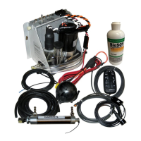
Pump Mounting Considerations
Consult the hydraulic-layout diagrams starting on page 6 to
help determine the pump-installation location.
• The pump must be mounted at a location to which you can
extend the hydraulic steering lines of the boat.
• The pump has five hydraulic-connector fittings, although only
three are used when installing the pump as recommended.
The illustration on page 2 may be helpful when
determining the fitting layout that is best for your installation
location.
Pump Hydraulic Considerations
NOTICE
When adding hydraulic line to the system, use only hose with
machine-crimped or field-replaceable fittings that have a
minimum rating of 1000 lbf/in² (6,895 kPa).
Do not use plumber’s tape on any hydraulic fitting. Use an
appropriate thread sealant rated for marine use on all pipe
threads in the hydraulic system.
Do not attempt to use the autopilot to steer the boat until you
bleed all air from each part of the hydraulic system.
Consult the hydraulic-layout diagrams starting on page 6 to
help determine how to best install the pump in the hydraulic
system of the boat.
The recommended pump installation method requires the
installation of T-fittings and shutoff valves so the pump can be
removed for service without disabling the steering system. This
type of installation will use only three of the five ports on the
manifold. Although it is not recommended, all five ports can be
used instead of installing shutoff valves. See page 2 for more
information on the fittings and alternate connection methods.
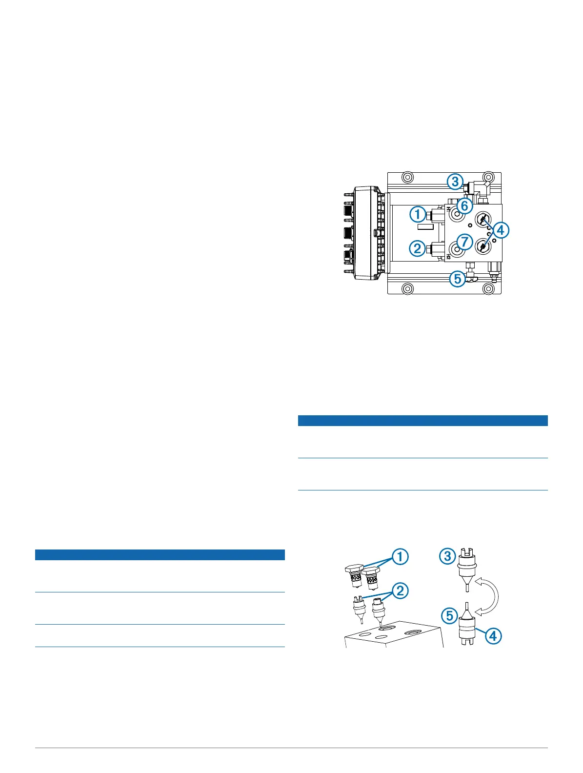
Pump Valves and Fittings
The pump can be connected to the hydraulic system using one
of two methods. The recommended three-connector method
uses only the C1
À
and C2
Á
fittings, with a T-connector
splitting the connection between the helm and cylinder. The
return line fitting
Â
connects to only the helm. The check valves
Ã
should not be reconfigured if the boat is equipped with a
balanced cylinder. If the boat is equipped with an unbalanced
cylinder, the check valves must be reconfigured (page 2).
The bypass valve
Ä
is opened only for hydraulic bleeding, and
must be fully tightened during normal operation.
If necessary, the H1
Å
and H2
Æ
fittings can be used with the
recommended three-connector installation instead of the C1
and C2 fittings.
Alternatively, the pump can be installed using all five
connectors. This installation option uses the C1 and C2 fittings
to connect the pump to the cylinder and the H1 and H2 fittings
to connect the pump to the helm. This type of installation is not
recommended, because the pump cannot be removed for
service without disabling the steering system of the boat.
Configuring the Pump for an Unbalanced Cylinder
NOTICE
To avoid damage to the pump, keep all parts clean and free of
dust and debris while configuring the pump for an unbalanced-
cylinder steering system.
If you remove the check valves after bleeding the hydraulic
system, you must bleed it again. Reconfiguring the check valves
may introduce air into the hydraulic system.
If the boat has an unbalanced cylinder steering system, you
must configure the pump to work properly with the steering
system.
1
Remove the check valves
À
from the pump manifold.
2
Pull the pistons
Á
out of the pump manifold.
The pump is configured from the factory with the pistons in
the balanced configuration
Â
.
3
Remove the o-rings
Ã
from the pistons and discard them.
If you cannot easily pull the o-rings from the pistons, you
may need to cut them.
2

 Loading...