GMC 7XX Installation Manual Page 4-1
190-00303-70 Revision F
4 SYSTEM INTERCONNECTS
4.1 Pin Function List
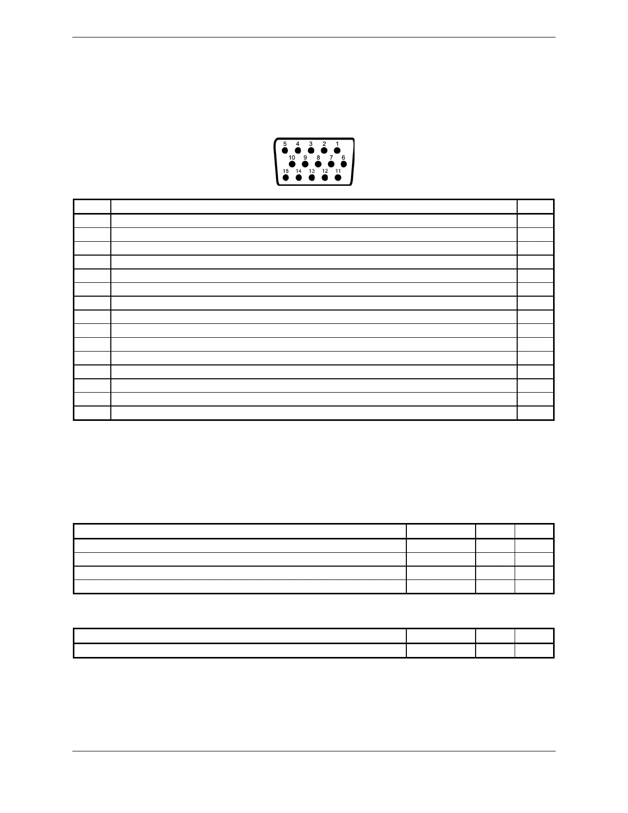
4.1.1 P7101
View of J7101 connector from back of unit
Pin Pin Name I/O
1 RS-232 OUT 1 Out
2 RS-232 IN 1 In
3 RS-232 OUT 2 Out
4 RS-232 IN 2 In
5 POWER GROUND --
6 SIGNAL GROUND --
7 AIRCRAFT POWER 1 In
8 SIGNAL GROUND --
9 AIRCRAFT POWER 2 In
10 CONTROL UNIT REMOTE POWER OFF In
11 LIGHTING BUS HI In
12 LIGHTING BUS LO In
13 RESERVED --
14 RESERVED --
15 POWER GROUND --
4.2 Power
4.2.1 Power Functions
This section covers the power input requirements.
4.2.1.1 Aircraft Power
Pin Name Connector Pin I/O
AIRCRAFT POWER 1 P7101 7 In
AIRCRAFT POWER 2 P7101 9 In
POWER GROUND P7101 5 --
POWER GROUND P7101 15 --
AIRCRAFT POWER 1 and AIRCRAFT POWER 2 are “diode ORed” to provide power redundancy.
4.2.1.2 Remote Power Off
Pin Name Connector Pin I/O
CONTROL UNIT REMOTE POWER OFF P7101 10 In
This input is used to power down the GMC 7XX, by a remote source. An input voltage between 6.5 Vdc
and 33 Vdc will power-off the GMC 7XX. An input voltage of 3.5 Vdc or less will turn the GMC 7XX
on.

 Loading...