GE Power Management 745 Transformer Management Relay 5-73
5 SETPOINTS 5.6 S4 ELEMENTS
5
c) INSULATION AGING SETPOINTS
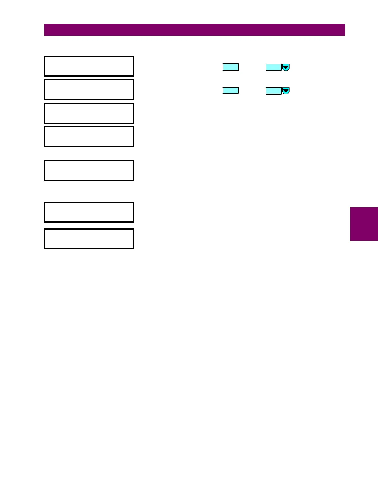
y INSULATION AGING
y
[ENTER] for more
This message indicates the start of the
INSULATION AGING
section. To
continue these setpoints press or press for the next section.
y HOTTEST-SPOT LIMIT
y
[ENTER] for more
This message indicates the start of the
HOTTEST-SPOT LIMIT
section. To
continue these setpoints press or press for the next section.
HOTTEST-SPOT LIMIT
FUNCTION: Disabled
Range: Disabled / Enabled
HOTTEST-SPOT LIMIT
TARGET: Self-Reset
Range: Self-reset / Latched / None
Select
None
to inhibit the display of the target message when the element
operates. Thus an element whose “target type” is
None
never disables the
LED self-test feature since it cannot generate a displayable target message.
HOTTEST-SPOT LIMIT
PICKUP: 150ºC
Range: 50 to 300 (steps of 1)
Enter the Hottest-spot temperature required for operation of the element.
This setting should be a few degrees above the maximum permissible
hottest-spot temperature under emergency loading condition and maximum
ambient temperature.
HOTTEST-SPOT LIMIT
DELAY: 10 min.
Range: 0 to 60,000, steps of 1 minute
Enter a time delay above which the hottest-spot temperature must remain
before the element operates.
HOTTEST-SPOT LIMIT
BLOCK: Disabled
Range: Disabled / Logc Inpt 1 (2-16) /Virt Inpt 1 (2-16) / Output Rly 1 (2-8) /
SelfTest Rly / Virt Outpt 1 (2-5)
ENTER
MESSAGE
ENTER
MESSAGE
 Loading...


