8-74 745 Transformer Management Relay GE Power Management
8.3 MODBUS MEMORY MAP 8 COMMUNICATIONS
8
8.3.2 MEMORY MAP DATA FORMATS
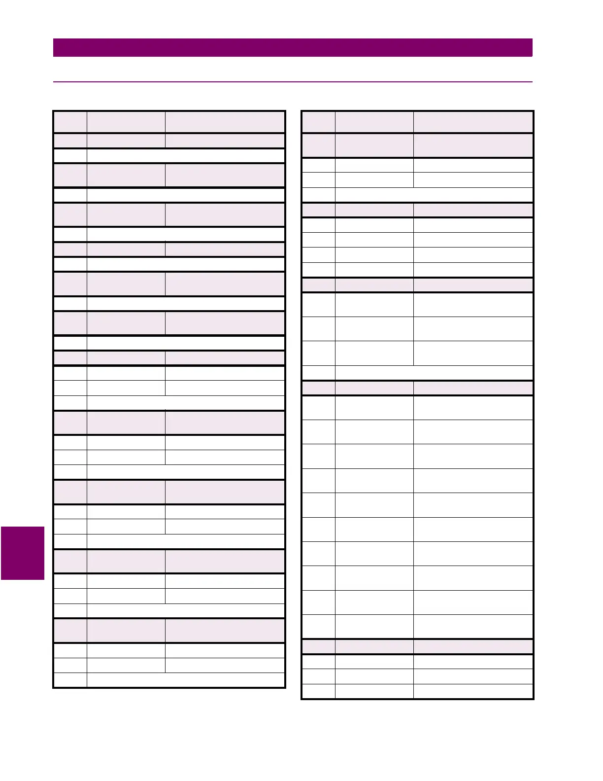
Table 8–7: 745 DATA FORMATS (Sheet 1 of 35)
FORMAT
CODE
APPLICABLE BITS DEFINITION
F1 16 bits UNSIGNED VALUE
Example: 1234 stored as 1234
F2 16 bits UNSIGNED VALUE
1 DECIMAL PLACE
Example: 123.4 stored as 1234
F3 16 bits UNSIGNED VALUE
2 DECIMAL PLACES
Example: 12.34 stored as 1234
F4 16 bits 2's COMPLEMENT SIGNED VALUE
Example: –1234 stored as –1234
F5 16 bits 2's COMPLEMENT SIGNED VALUE,
1 DECIMAL PLACE
Example: –123.4 stored as –1234
F6 16 bits 2's COMPLEMENT SIGNED VALUE,
2 DECIMAL PLACES
Example: –12.34 stored as –1234
F7 32 bits UNSIGNED LONG VALUE
1st 16 bits high order word of long value
2nd 16 bits low order word of long value
Example: 123456 stored as 123456
F8 32 bits UNSIGNED LONG VALUE,
1 DECIMAL PLACE
1st 16 bits high order word of long value
2nd 16 bits low order word of long value
Example: 12345.6 stored as 123456
F9 32 bits UNSIGNED LONG VALUE,
2 DECIMAL PLACES
1st 16 bits high order word of long value
2nd 16 bits low order word of long value
Example: 1234.56 stored as 123456
F10 32 bits 2's COMPLEMENT SIGNED LONG
VALUE
1st 16 bits high order word of long value
2nd 16 bits low order word of long value
Example: -123456 stored as -123456
F11 32 bits 2's COMPLEMENT SIGNED LONG
VALUE, 1 DECIMAL PLACE
1st 16 bits high order word of long value
2nd 16 bits low order word of long value
Example: –12345.6 stored as –123456
F12 32 bits 2's COMPLEMENT SIGNED LONG
VALUE, 2 DECIMAL PLACES
1st 16 bits high order word of long value
2nd 16 bits low order word of long value
Example: –1234.56 stored as –123456
F13 16 bits HARDWARE REVISION
0000 0000 0000 0001 1 = A
0000 0000 0000 0010 2 = B
↓
↓
0000 0000 0001 1010 26 = Z
F14 16 bits SOFTWARE REVISION
xxxx 1111 xxxx xxxx Major Revision Number
0 to 9 in steps of 1
xxxx xxxx 1111 xxxx Minor Revision Number
0 to 9 in steps of 1
xxxx xxxx xxxx 1111 Ultra Minor Revision Number
0 to 9 in steps of 1
Example: Revision 2.83 stored as 0283 hex
F15 16 bits INSTALLED OPTIONS
xxxx xxxx xxxx xxx1 Windings Per Phase (0 = Two
Windings, 1 = Three Windings)
xxxx xxxx xxxx xx1x Rating of Winding 1 Phase Current
Inputs (0 = 1 A, 1 = 5 A)
xxxx xxxx xxxx x1xx Rating of Winding 2 Phase Current
Inputs (0 = 1 A, 1 = 5 A)
xxxx xxxx xxxx 1xxx Rating of Winding 3 Phase Current
Inputs (0 = 1 A, 1 = 5 A)
xxxx xxxx xxx1 xxxx Rating of Winding 1/2 Ground
Current Inputs (0 = 1 A, 1 = 5 A)
xxxx xxxx xx1x xxxx Rating of Winding 2/3 Ground
Current Inputs (0 = 1 A, 1 = 5 A)
xxxx xxxx x1xx xxxx Control Power (0=LO [20-60 Vdc],
1 = HI [90-300 Vdc/70-265 Vac])
xxxx xxxx 1xxx xxxx Analog Input/Outputs (0 = Not
Installed, 1 = Installed)
xxxx xxx1 xxxx xxxx Loss-Of-Life (0 = Not Installed,
1 = Installed)
xxxx xx1x xxxx xxxx Restricted Ground Fault (0 = Not
Installed, 1 = Installed)
F16 16 bits DEMAND INTERVAL/RESPONSE
0000 0000 0000 0000 0 = 5 min
0000 0000 0000 0001 1 = 10 min
0000 0000 0000 0010 2 = 15 min
Table 8–7: 745 DATA FORMATS (Sheet 2 of 35)
FORMAT
CODE
APPLICABLE BITS DEFINITION
 Loading...


