GE Power Management 745 Transformer Management Relay 5-5
5 SETPOINTS 5.2 AUTO-CONFIGURATION
5
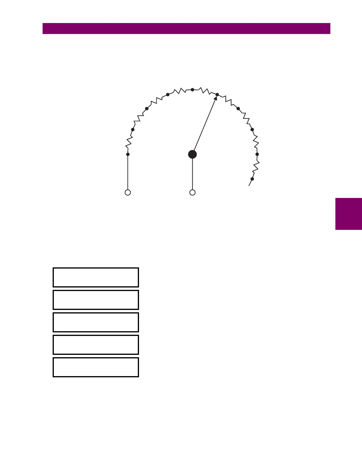
Tap changers are operated by means of a motor drive unit mounted on the outside of the transformer tank. The
motor drive is placed in a protective housing containing all devices necessary for operation, including a tap
position indication circuit. This indication circuit has a terminal for each tap with a fixed resistive increment per
tap. A cam from the drive shaft that provides local tap position indication also controls a wiper terminal in the
indication circuit, as illustrated below.
Figure 5–1: TAP POSITION INPUT
The “zero position” terminal and the “wiper” terminal of the tap position circuit are connected to the positive and
negative 745 tap position terminals. Polarity is not consequential. The following setpoints configure the 745 to
determine tap position.
Under
S2 SYSTEM SETUP / ONLOAD TAP CHANGER
:
WINDING WITH TAP
CHANGER: Winding 2
NUMBER OF TAP
POSITIONS: 33
MINIMUM TAP POSITION
VOLTAGE: 61.0 kV
VOLTAGE INCREMENT
PER TAP: 0.50 kV
RESISTANCE INCREMENT
PER TAP: 33
Ω
Maximum value resistance on top tap is 5 K
Ω
ZERO
POSITION
TAP 1
TAP 2
TAP 3
TAP 4
TAP 6
TAP 7
TAP 8
TAP 9
etc.
WIPER
AT TAP 5
R
R
R
RR
R
R
R
R
ZERO POSITION
TERMINAL
(to TAP POSITION -)
WIPER
TERMINAL
(to TAP POSITION +)
 Loading...


