GEI-86151
B
OPERATION
GENERAL
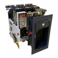
The AKR-75
and
AKR'100
breakers
are
closed
by the
discharging
of the
energy stored
in the closing
springs
of the
breaker.
As the closing
springs
are discharged,
the
energy
is
directed
into
the
closing
cam
of
the breaker
which causes
the
moveable breaker
contacts
to be
forced against
the station-
ary
contacts, and, at
the same
time causes
the opening
springs
to be charged
so they
may open
the breaker
during
a
subsequent
opening
operation.
MANUAL CLOSING
Manually operated
breakers
are equipped
with a
handle
whlch extends
from the escutcheon
of the
breaker.
Alter-
nately rotating the
closing handle counterclockwise
then
clockwise
through approximately
120
degrees of
rotation
through
four complete
cycles will cause
the breaker
to close.
During the four counterclockwise
movements and the
first
three clockwise
movements of
the handle,
the springs are
progressively
charged.
After approximately
seven degrees
travel of the
fourth clockwise handle
movement,
the
spring
charge mechanism
is driven
"over
center" and
the energy
stbred
in
the closing
springs
is
directed
into the closing cam
and causes
the breaker
to
close.
A charge-indicator,
num-
bered one to four, visible through the breaker
escutcheon.
indicates the number of comolete
handle movements that
have
been oerformed.
r--
I
x
lI--
I
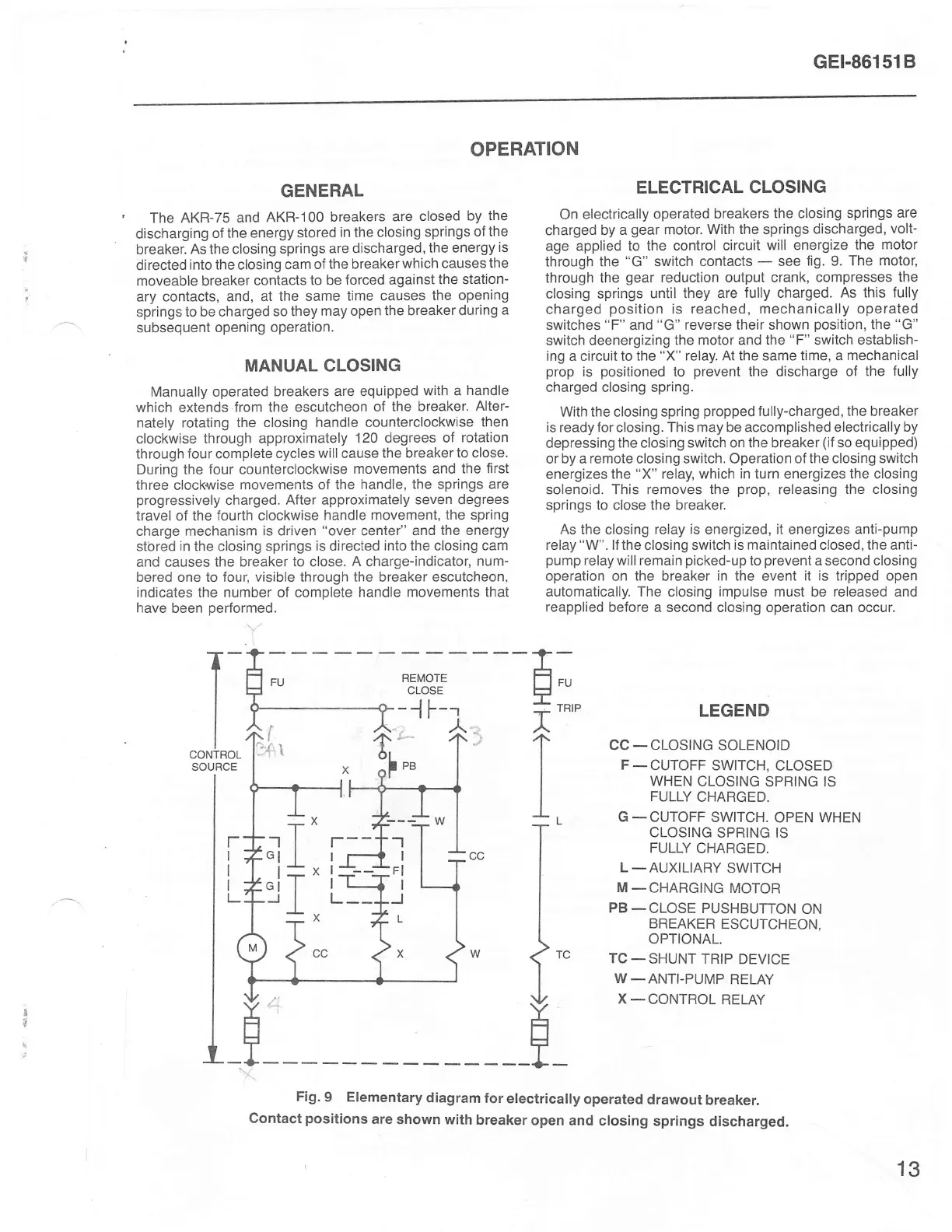
ELECTRICAL
CLOSING
On
electrically
operated breakers
the
closing
springs
are
charged
by a
gear
motor.
With the springs
discharged,
volt-
age
applied to the
control circuit
will energize
the
motor
through the
"G"
switch
contacts
-
see
fig. 9.
The motor,
through the
gear
reduction output crank, compresses
lhe
closing springs
until they are
fully charged.
As this fully
charged
position
is reached, mechanically operated
switches
"F"
and
"G"
reverse their shown
position,
the
"G"
switch
deenergizlng the motor and the
"F"
switch
establish-
ing
a circuit
to the
"X"
relay.
At the
same
time, a
mechanical
prop
is
positioned
to
prevent
the discharge
of the
fully
charged closing spring.
With
the
closing spring
propped
fully-charged, the breaker
is ready for closing. This
may
be accomplished electrically
by
depressing
the closing switch on the breaker
(if
so equipped)
or by a
remote
closing switch. Operation
of the closing switch
energizes
the
"X"
relay, which
in
turn energizes the closing
solenoid. This removes
the
prop,
releasing the closing
springs to
close
the breaker.
As the closing relay
is
energized,
it
energizes
anti-pump
relay
"W".
lf the
closing
switch is maintained closed, the anti-
pump
relay will remain
picked-up
to
prevent
a second closing
operation on
the
breaker
in the
event
it is tripped open
automatically. The closing impulse must be released and
reapplied
before a second closing operation
can
occur.
LEGEND
CC_CLOSING
SOLENOID
F
-
CUTOFF
SWITCH,
CLOSED
WHEN
CLOSING
SPRING
IS
FULLY
CHARGED.
G
_CUTOFF
SWITCH.
OPEN WHEN
CLOSING
SPRING IS
FULLY
CHARGED.
L
_AUXILIARY
SWITCH
M
_CHARGING
MOTOR
PB_CLOSE
PUSHBUTTON
ON
BREAKEB
ESCUTCHEON,
OPTIONAL.
TC
_
SHUNT TRIP
DEVICE
W_ANTI-PUMP
RELAY
X_CONTROL
RELAY
t
,{,1
T_
I
I
I
CONTROL
SOURCE
-1T
"lI
1J
F
H:
r''
I
I
I
i"
F-
-'l
I
Fl
I
J
Fig.
9 Elementary
diagram
for
electricaily
operated
drawout
breaker.
contact
positions
are shown
with
breaker
open
and closing
springs discharged.
13
 Loading...