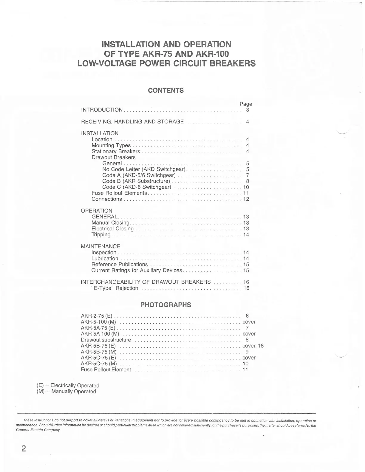
INSTALLATION AND
OPERATION
OF
TYPE AKR.75 AND AKR-IOO
LOW.VOLTAGE POWER
CIRCUIT
BREAKERS
CONTENTS
Page
TNTRODUCTTON... .......
3
RECEIVING.
HANDLING AND STOFIAGE ... 4
INSTALLATION
Location
.......4
MountingTypes. ......4
Stationary Breakers . .. .
4
Drawout Breakers
General
5
NoCodeLetter(AKDSwitchgear) .......
5
Code A
(AKD-5/6
Switchgear) 7
CodeB(AKRSubstructure) ......
8
CodeC
(AKD-6Switchgear)
...,.10
Fuse Rollout Elements. .......11
Connections
....12
OPERATION
GENERAL. .....13
Manual Closing. .......13
ElectricalClosing ......13
Tripping
........14
MAINTENANCE
lnspection ......14
Lubrication .....14
Reference Publications
.......15
CurrentRatingsforAuxiliaryDevices ........15
INTERCHANGEABILITY OF DRAWOUT BREAKERS .......... 16
"E-Type"
Rejection
....16
PHOTOGRAPHS
AKR-2-75
(E)
. 6
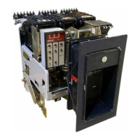
AKR-5-100(M)
...cover
AKR-5A-75(E) ..
7
AKR-5A-100(M) .. .. cover
Drawout
substructure
I
AKR-5B-75(E) ...
.. cover,18
AKR-58-75(M).
........ e
AKR-5C-75(E) ... ..cover
AKR-5C-75(M). ........10
FuseRolloutElement ......11
(E)
:
Electrically
Operated
(M)
:
Manually
Operated
Theseins|ructionsdonotpurporttocove|a|ldetailso|variationsinequipmentnortoprovidetoreverypossib|econtingencytobemetinconnetion
maintenance'shouldfuiherin|ormationbedesirdo|shouldparticUlarprblemsaisewhicharenotcovaredsu|fcie
Genetal Electilc Company.
z
 Loading...