GEt-86151
B
Before inst'alling or operating these circuit breakers, care-
fully read these
instructions.
Upon
receipt of a circuit breaker, immediately examine
for
any damage or
loss sustained in shipment. lf
injury,
loss
or
rough
handling
is
evident,
file
a
damage claim at once with
the
transportation
company
and notify the nearest General
Electric Sales Office.
Unoack
the circuit breaker as soon as
possible
after it has
been
received. Exercise care in unpacking to avoid damage
to the
breaker
parts.
Be
sure that
no loose
parts
are
missing
RECEIVING, HANDLING AND
STORAGE
INSTALLATION
or
left in the
packaging
material. Blow out any dirt or
loose
particles
of
packaging
material remaining on or
in
the
breaker.
lf
the circuit breaker
is not to be
placed
in
service
at once,
store
it
in a clean, dry location
in
an
upright
position.
Support
it to
prevent
bending
of the
studs
or damage
to
any of
the
breaker
parts.
Do not
cover
the breaker
with
packing
or other
material which
absorbs
moisture that may
cause
corrosion of
breaker
parts.
A covering of kraft or other non-absorbent
paper
will
prevent
dust from
settling on
the breaker.
NOTE: Before installing in
a Nuclear C/ass 7E
application, verify that
this
product
is
intended for
such use
by checking
the
procurement
records.
LOCATION
In choosing
a
location
for the installation
of
these
breakers
there
are two factors
to
be considered.
The first is
the
location's
environmental impact
on the
breaker. Much better
performance
and longer life
can
be expected if the
area
is
clean,
dry, dust-free and well ventilated.
The second
is con-
venience
for
operation and maintenance.
The
breaker
should
be easily accessible
to the
operator and there
should
be sufficient
space
available
for
maintenance
work.
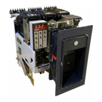
MOUNTING TYPES
AKR-75
and
-100
breakers
are furnished in
both
drawout
and
stationary
construction. The mounting
type is identified
by
the second middle digit in
the breaker's nameplate
desig-
nation
as
follows:
AKR-4(f)-75, where
(t)
:
mounting type
code letter
per
Table
2
STATIONARY BREAKERS
These breakers are designed
for mountlng in
a switch-
board or enclosure designed
and
constructed by others.
Mounting consists of bolting the breaker frame to a support-
ing
structure
within the switchboard or
enclosure, connecting
the
power
buses or cables, and making any necessary con-
trol connections.
The front
cover of the breaker enclosure
may be a hinged door or a
plate
bolted to the
panel,
including
a cut-out opening through
which
the
front
escutcheon of the
breaker can
protrude.
The
surface on
which
the breaker is mounted
must be flat
to avoid internal
distortion
of
thb
breaker. The
supporting
structure must
be
rigid
enough to
avoid
any
possibility
of
the
breaker
studs supporting the weight
of the breaker. Minimum
cutout dimensions
as
given
by the appropriate
outline
draw-
ing
must be maintained to
provide
adequate
electrical clear-
ance. Connecting
bus and cables must
be rigidly
supported
to
prevent
undue stress
on
the
breaker terminals.
Outline drawing numbers
giving
dimensions for
designing
a suitable enclosure
for the stationarv
AKR-75
and AKR-100
types are
given
below.
TABLE 2
MOUNTING
TYPE
CODES
AKR-75/100
(25"
wide)
AKR-100
(33"
wide)
TABLE
3
Stationary
Breaker
Type
Breaker
widrh
Outline Drawing
Manually
Operated
Electrically
Operated
AKR-(
)S-75
25"
1
39C456C
AKR-(
)S-100
25"
139L;4561
AKR-(
)W-100
33" 1
39C456i 139C4563
4
 Loading...