Troubleshooting
ENGLISH
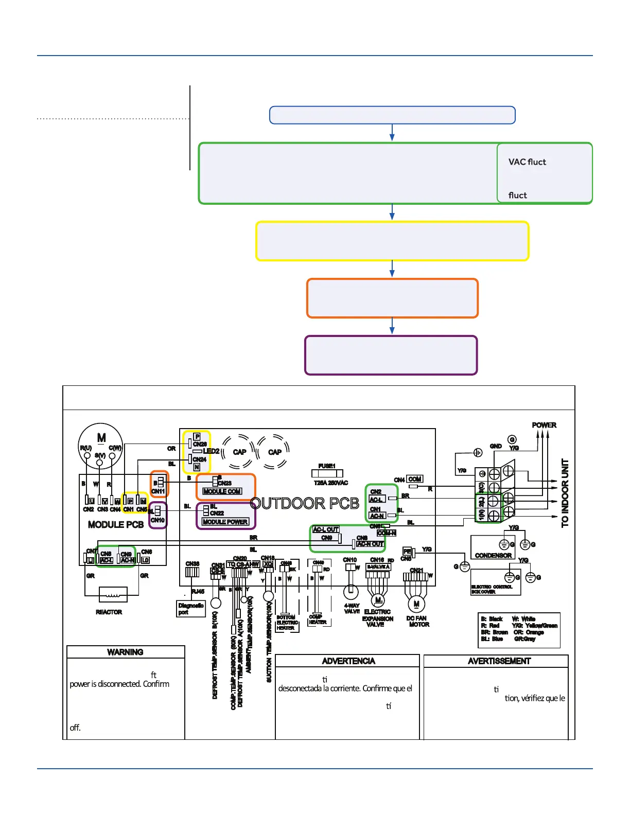
Outdoor Board Diagram
09K
12K-18K
OUTDOOR UNIT WIRING DIAGRAM
0011509127A
OUTDOOR UNIT WIRING DIAGRAM
COMPRESSOR
Electrical Shock Hazard
Capacitor retains charge a
er
voltage at capacitor has dissipated
(<10V DC) with hand held voltmeter
before servicing. LED2 light
between CN24 and CN26 should be
Riesgo de Descarga Eléctrica
El capacitor re
ene carga una vez
voltaje del capacitor se haya disipado (<10V
DC) apoyando la mano sobre el
vol
metro
antes de realizar el servicio técnico. La luz
LED2 que se encuentra entre CN24 y CN26
deberá estar apagada.
Risque de choc électrique
Le condensateur conserve sa charge après la
coupure de l’alimenta
on électrique. Avant
de procéder à une répara
courant au condensateur s’est dissipé
(<10 VCC) à l’aide d’un voltmètre manuel. Le
voyant LED2 entre CN24 et CN26 doit être
éteint.
0011509127
Check This First
Outoor Unit
Models:
ASH109CRAWA
ASH112CRAWA
Line voltage available at:
1. TERMINAL STRIP - 1(N) & 2 (L)
2. AC-L & AC-N at the PCB - CN2 & CN1
3. AC-L OUT & AC-N OUT at the PCB - CN8 & CN9
4. AC-L & AC-N at the IPM -CN8 & CN9 (9K) / CN1 & CN2 (12K/18K)
310+ VDC available at:
1. P & N at the IPM - CN1 & CN5 (9K) / CN8 & CN9 (12K/18K)
2. P & N at the PCB - CN24 & CN26
Module COM 5-G-15 VDC available at:
1. CN23 at the PCB
2. CN11 at the IPM
Module power 5-G-15 VDC available at:
1. CN22 AT THE PCB
2. CN10 AT THE IPM
• 1 (N) and 3 (C): 0-80
uating
• 2 (L) and 3 (C):
0-140 VAC
uating
Wiring Diagram Reference
Conditions Needed for Basic Operation
3-minutes of time delay from the call for heating or cooling
ERROR CODES and Troubleshooting
PAGE 2
8
ASH118CRDWA
ASH124CRDWA
 Loading...