Troubleshooting
See reverse side for
wiring diagram and
relevant color-coded
test positions.
Yes
Yes
Yes
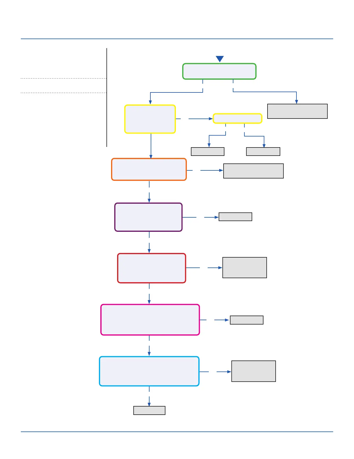
Start
No
No
No
No
No
Line voltage at AC-L & AC-N
on the PCB (CN2 & CN1)?
Line voltage at AC-L & AC-N
on the IPM (9K CN8 & CN9 /
12K/18K CN1 & CN2)?
Module Power voltage -
CN22 on the PCB:
Across pins 1 & 2 = 5VDC
Across pins 2 & 3 = 15VDC?
Module Power voltage -
CN10 on the IPM
Across pins 1 & 2 = 5VDC
Across pins 2 & 3 = 15VDC?
Module Com voltage - CN23 on the PCB
With a call for Heating or Cooling,
Across pins 1 & 2 = 5VDC
Across pins 2 & 3 = 15VDC ?
Module Com voltage - CN11 on the IPM
With a call for Heating or Cooling,
Across pins 1 & 2 = 5VDC
Across pins 2 & 3 = 15VDC?
Yes
Yes
Yes
No
Yes
No
Yes
No
Check incoming power
from building
Replace PCB
Replace PCB
Replace fuse
Replace AC-L & AC-N
wiring harness
Replace module
power wiring
harness
Replace Module
COM Wiring
Harness
Replace PCB
Replace IPM
Fuse 1 is OK?
Line voltage at
AC-L OUT & AC-N
OUT on the PCB
(CN8 & CN9)?
Error Code (Indoor/Outdoor)
F3/LED1: 4 Flash
Communication Fault Between IPM and
Outdoor PCB
Complete the “Check This First” Flow
Chart before continuing.
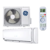
Models:
ERROR CODES and Troubleshooting
PAGE 35
ASYW09CRAWA
ASYW12CRAWA
ASYW18CRDWA
ASYW24CRDWA
ASH109CRAWA
ASH112CRAWA
ASH118CRAWA
ASH124CRAWA
 Loading...