18 31-5000483 Rev. 2
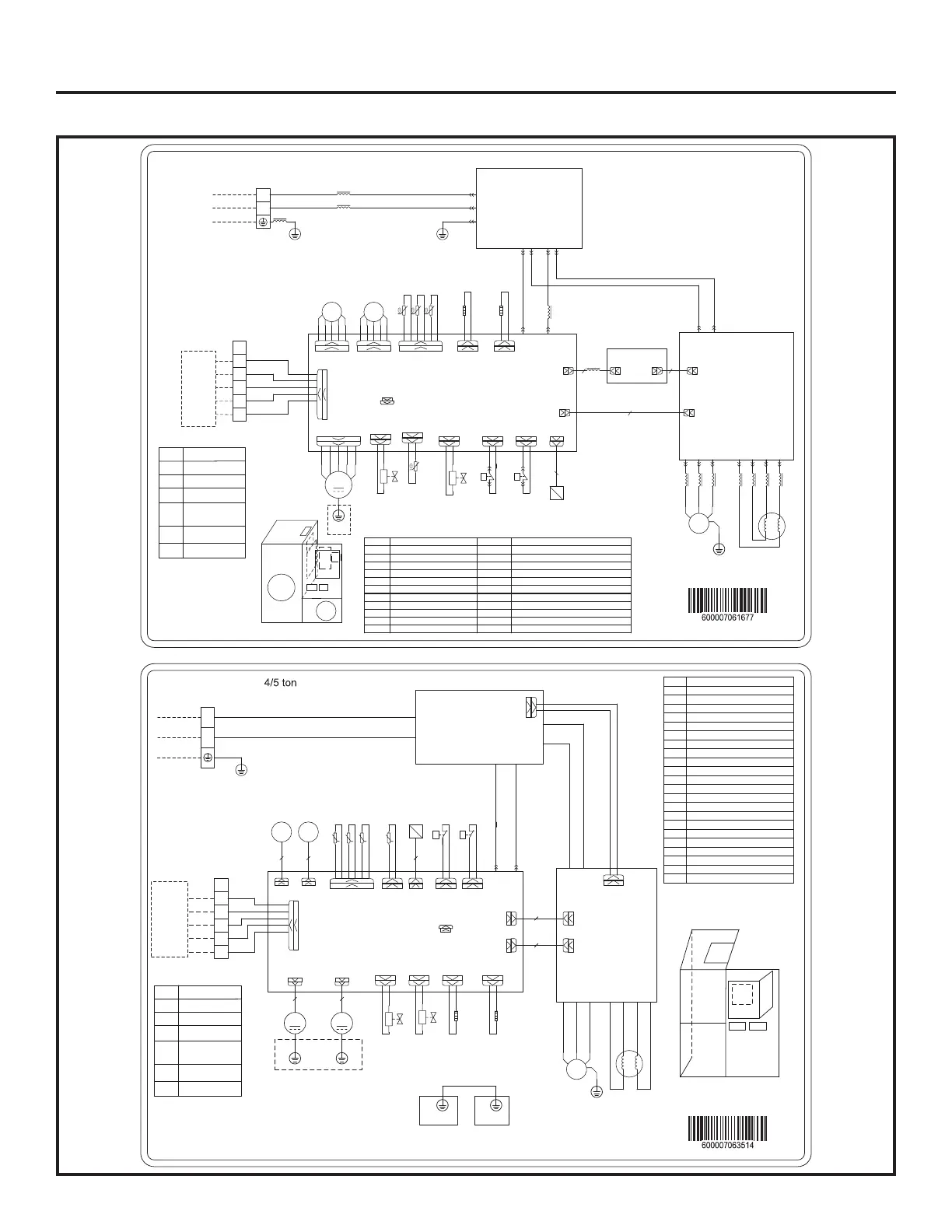
Wiring Diagram
Installation Instructions
L2
L1
G
POWER
L1
XT1
L2
AP3
X1 X2
EKV1
FA
P
HP
HEAT_TIE_C
EH1
T_SENSOR2
θ
20k
θ
15K
θ
50K
4WAY
4YV
AP1
E1
L-OUT
N-OUT
AC-L
AC-N
3~
G
W V U
COMP
U V W
Outdoor U nit- 2/3 ton
Electric Component Position Map
Symbol Name Symbol Name
COMP Compressor HPP High Pressure Switch
M1 Fan Motor H-PRESS High Pressure Sensor
AP1 Filter Board 4YV 4-Way Valve
AP2 Drive Board EKV1/EKV2 Electronic expansion valve coil 1/2
AP3 Control Board LPP Low Pressure Switch
AP4 Connection Board 2YV Electromagnetic Valve
XT1~XT2 Wiring Board RT1 Defrosting Temp.Sensor
EH1 Compressor Band Heater RT2 Environment Temp.Sensor
EH2 Bottom Band Heater RT3 Discharge Temp.Sensor
L1 Inductance RT Speed Adjustment Temp.Sensor
L PFC Inductor L2-L7 Magnet Ring
W1
W2
W3 W4
W7
T_LAC
AP2
AC-L N
L2-1
L1-1L1-2
L2-2
YE BN WH BU
L
L2
L2
L7
L3L4L4L3L5 L5 L5
L1
COMM1
COMM
4
RT1
RT2 RT3
G
G
BK
RD
M1
G
DC_MOTOR1
EKV2
FA1
SP
H-PRESS
3
VA
2YV
W21W20
W10
W11
W12
W13
W8
W22
W5 W6
W16 W17 W18
W19
AP4
W9
L6
PWR1
PWR1
PWR2
2 3
PWR
HPP
COM-MANUAL
M1
AP3
AP2
XT1
XT2
AP4
COMP
AP1
L1
L
C
R
W1
B
Y
XT2
Note:1. Jumper cap needs to be connected if the re is a jumper cap on unit ’ S main board .
2. ①Only applicable for the unit with iron shell motor .
W14
HEAT_TIE_B
EH2
θ
20K
RT
G
Thermostat
P
LP
LPP
W23
W24
JUMP
①
Code
Name
C
R
W1
B
Y
24V common
24V AC power supply
Defrosting signal
4-way valve control
signal,energized under
the heating mode
Compressor control
signal
G
—
Power
X1
X2
HEAT_TIE_C
EH1
T_SENSOR2
4WAY
YV1
3~
G
W V U
COMP
Outdoor unit - 4/5 ton
1
2
3
T_LAC
L
RT1
RT2RT3
G
SP
H-PRESS
VA
YV2
LPP
COM-MANUAL
C
R
W1
B
Y
Note:①Only applicable for the unit
whose motor is with earthing wire
HEAT_TIE_B
EH2
20K
XT2
Thermostat
HPP
JUMP
①
L1
L2
L1
XT1
L1
L2
接地
L2 AP1 N
接地
AP1
AC-L
N
L-OUT
N-OUT
L-OUT1
N-OUT1
DC-BUS
AP2
AC-L
N
U V W
L1-1 L1-2 L2-1 L2-2
DC-BUS
COMM
AP3
θ θ θ θ
EKV1 EKV2
FA FA1
P
HP
P
LP
M1
G
M2
G
DC-MOTOR1 DC-MOTOR2
COMM1
5
5
5 5
4
3
4 5 6 7
8
9
10
12 13 14
15
16
17
18
19
20
21
22 23 24
BN WH YE
BU
G
CODE NAME
20K Speed adjustment temperature sensor
AP1 Filter board
AP2 Drive board
AP3 Main control board
SP High pressure sensor
COMP Compressor
EH1 Electric heating belt of compressor
EH2 Electric heating belt of chassis
EKV1 Electronic expansion valve 1
EKV2 Electronic expansion valve 2
HP High pressure switch
L Inductor
LP Low pressure switch
M1 DC-MOTOR1
M2 DC-MOTOR2
RT1 Defrosting temperature sensor
RT2 Ambient temperature sensor
RT3 Discharge temperature sensor
XT1 Wiring board
XT2 Wiring board
YV1 4-way valve
YV2 Solenoid valve
PWR1
PWR
2
11
L
AP3
AP1
AP2
XT1
XT2
M1
M2
Component layout
Code
Name
C
R
W1
B
Y
24V common
24V AC power supply
Defrosting signal
4-way valve control
signal,energized under
the heating mode
Compressor control
signal
Electric box
Radiator
25
G G
G
—
AUH2436ZGDA
AUH4860ZGDA
 Loading...