Installingthe dryer.
Exhaust Ducting Length
Tim exhaust system should be inspected and cleaned
at least once a year with normal usage. Tile more the
dryer is used, tbe more often you should check 1he
exhaust system and vent hood for proper operation.
If roof vents or louvered plenums are used, 1hey must
be equivalent to a 4" dampered wall cap in regard to
resistance to airflow, prevention of back drafts and
maintenance required to prevent clogging.
• DONOTassemble tbe duct workwitb thsteners that
extend into the duct. Timy will serve as collection
points for lint.
• Ductwork which runs through an unheated area or
is near an air conditioning duct should be insulated
to reduce condensation and lint build-up.
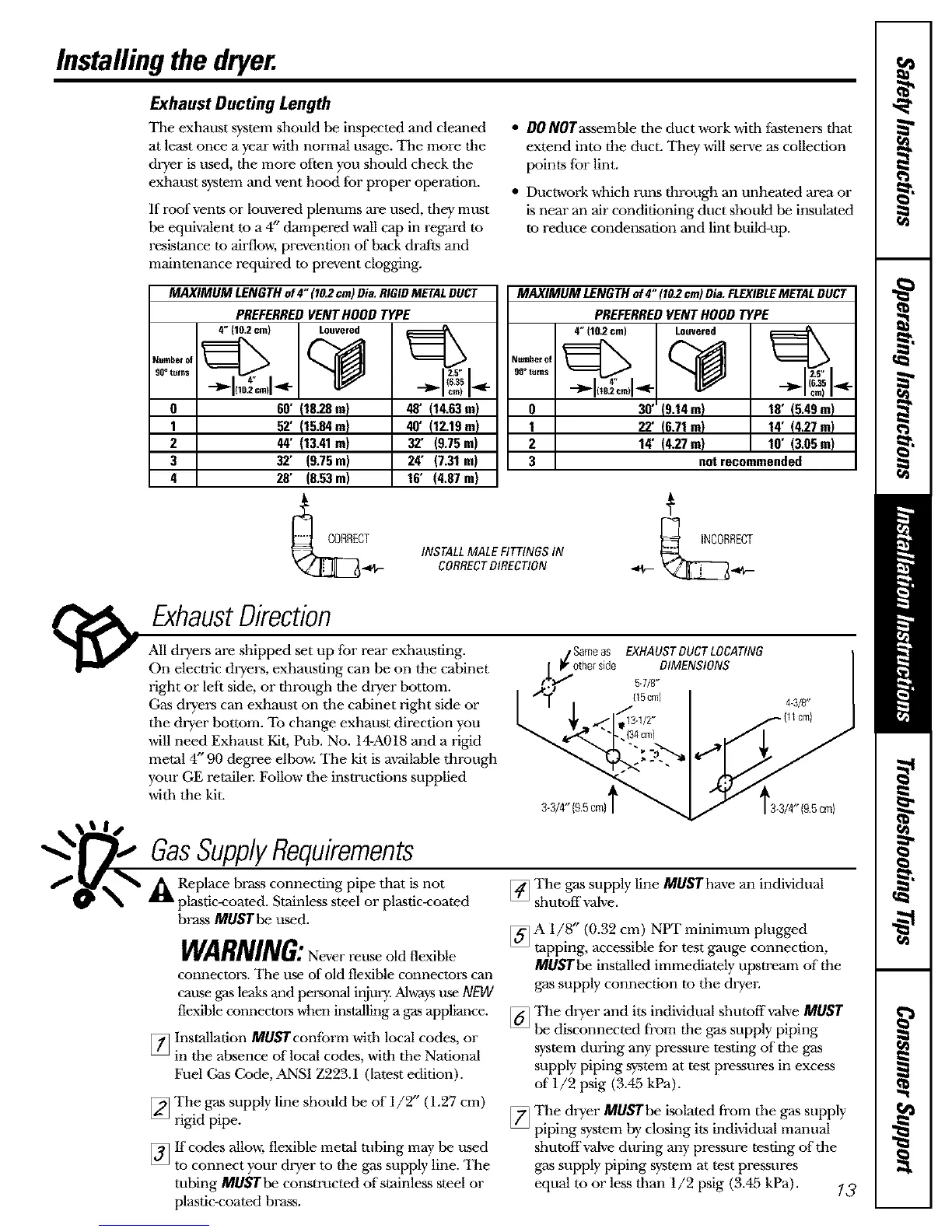
MAXIMUM LENGTH of4" (10.2cm) Dia. RIGIDMETALDUCT
Number ol
00° tllrBS
0
1
2
3
4
PREFERREDVENTHOODTYPE
4" (10.2cm) Louvered
60' {18.28In)
52' (15.84m)
44' (13.41In)
32' (9.75In)
28' (8.53m)
48' (14.63In)
40' (12.19In)
32' (9.75In)
24' (7.31In)
16' (4.87 In)
MAXIMUM LENGTH of 4" (10.2cm)Dia. FLEXIBLEMETALDUCT
Number of
90° ullns
O
1
2
3
INSTALLMALE FITTINGSIN
CORRECTDIRECTION
PREFERREDVENTHOODTYPE
4" 110.2cm) Louvered
30"{9.14In)
22' {6.71In)
14' (4.27In)
18' (5.49In)
14' (4.27In)
10' (3.05In)
not recommended
ExhaustDirection
All dryers are shipped set up for rear exhausting, j Sameas EXHAUSTDUCTLOCATING I
On electric dryers, exhausting can be on the cabinet _ It,"otherride DIMENSIONS
t._,,,'I 5.7/8"
right or left side, or through tim dryer bottom. I _,,_S I (15cm) 44/8"
Gas dryei,'s can exhaust on the cabinet right side or
L _t ,./1_j_3.v2" _{u_m) /
tim dryer bottom. To change exhaust direction you
will need Exhaust Kit, Pub. No. 14-A018 and a rigid
metal 4" 90 degree ell,'ow. Tim kit is available through _'_-._ __
your GE rerailm: Follow tbe instructions supplied
witb the kit. S-3/4"{9.5cm}f _ Z 13-3/4"(9£ crn}
GasSupplyRequirements
A Replace brass connecting pipe that is not
plastic-coated. Stainless steel or plastic-coated
brass MUSTbe used.
[]
WARNING:Neverrouseoldflexible
connectors. The use of old flexible connectors can
cause gas leaks and personal injmy_Alwa)_use NEW
flexible connectors when inslalling a gas appliance.
Installation MUSrconform witb local codes, or
in tbe absence of local codes, with tbe National
Fuel Gas Code, ANSI Z223.1 (latest edition).
[]
[]
The gas supply line should be of 1/2" (1.27 cm)
rigid pipe.
If codes allow, flexible metal tubing may be used
to connect your dryer to the gas supply line. The
tubing MUSTbe consrructed of stainless steel or
plastic-coated brass.
_The gas supply line MUSThave an individual
shutoff waive.
_A 1/8" (0.32 cm) NPT minimum plugged
tapping, accessible 1or test gauge connection,
MUSTbe installed immediately upstream of the
gas supply connection to tim dryer.
_The dryer and its individual shutoffwalve MUST
be disconnected from the gas supply piping
system during any pressure testing of the gas
supply piping system at test pressures in excess
of 1/9 psig (3.45 kPa).
]The dryer MUSTbe isolated from tim gas supply
piping system by closing its individual manual
shutoff waiveduring any pressure testing of the
gas supply piping system at test pressures
equal to or less tban 1/2 psig (3.45 kPa). 13
 Loading...