Modifications reserved Page 36/99
OPM_SPE_XXX_10K_40K_8GB_V020.doc Operating Manual SitePro 10-15-20-30-40 kVA / S8
5.9 RPA PARALLEL SYSTEM CONNECTION
WARNING !
This operation must be performed by trained personnel before the initial start-up
(ensure that the UPS installation is completely powered down).
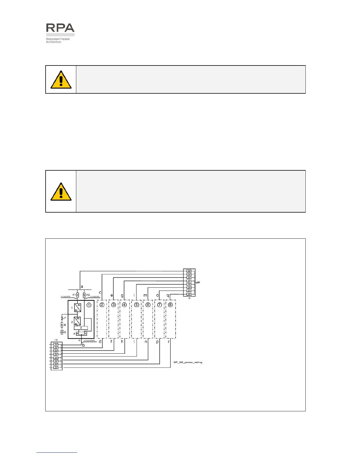
5.9.1 Power wiring of parallel units
To guarantee good Load sharing between the units of a Parallel System, we recommend that the cable
length from the input distribution board (5) to the output distribution board (10) is equal for each unit
(a+b = c+d = e+f = g+h = i+l = m+n = o+p = q+r).
Tolerance: +/-10%.
The AC input power of the Bypass must be the same for all UPS units of the Parallel System - no phase
shift allowed between units.
NOTE !
It is strongly recommended that no transformers, automatic circuit breakers or fuses
should be inserted between the unit’s output and the Load common bus bars.
However, it is recommended that a disconnection or isolation switch is installed in
order to totally isolate a unit if needed.
Verify that power wiring and control wiring run in separate conduits or cable trays.
The power wiring requires two separate conduits: one for input and one for output cables.
1 = Rectifier
2 = Inverter
3 = Electronic bypass
4 = Manual bypass
5 = Input mains distribution
6 = Unit output load
7 = External battery MCB
8 = External battery fuse
9 = External battery
10 =
Common bus bar &
Output load distribution
= UPS number 1
2
= UPS number 2
3
= UPS number 3
4
= UPS number 4
5
= UPS number 5
6
= UPS number 6
7
= UPS number 7
Fig. 5.9.1-1 Power wiring of RPA Parallel System
8
= UPS number 8
 Loading...


