Modifications reserved Page 85/99
OPM_SPE_XXX_10K_40K_8GB_V020.doc Operating Manual SitePro 10-15-20-30-40 kVA / S8
9 CUSTOMER INTERFACE
9.1 CUSTOMER INTERFACE
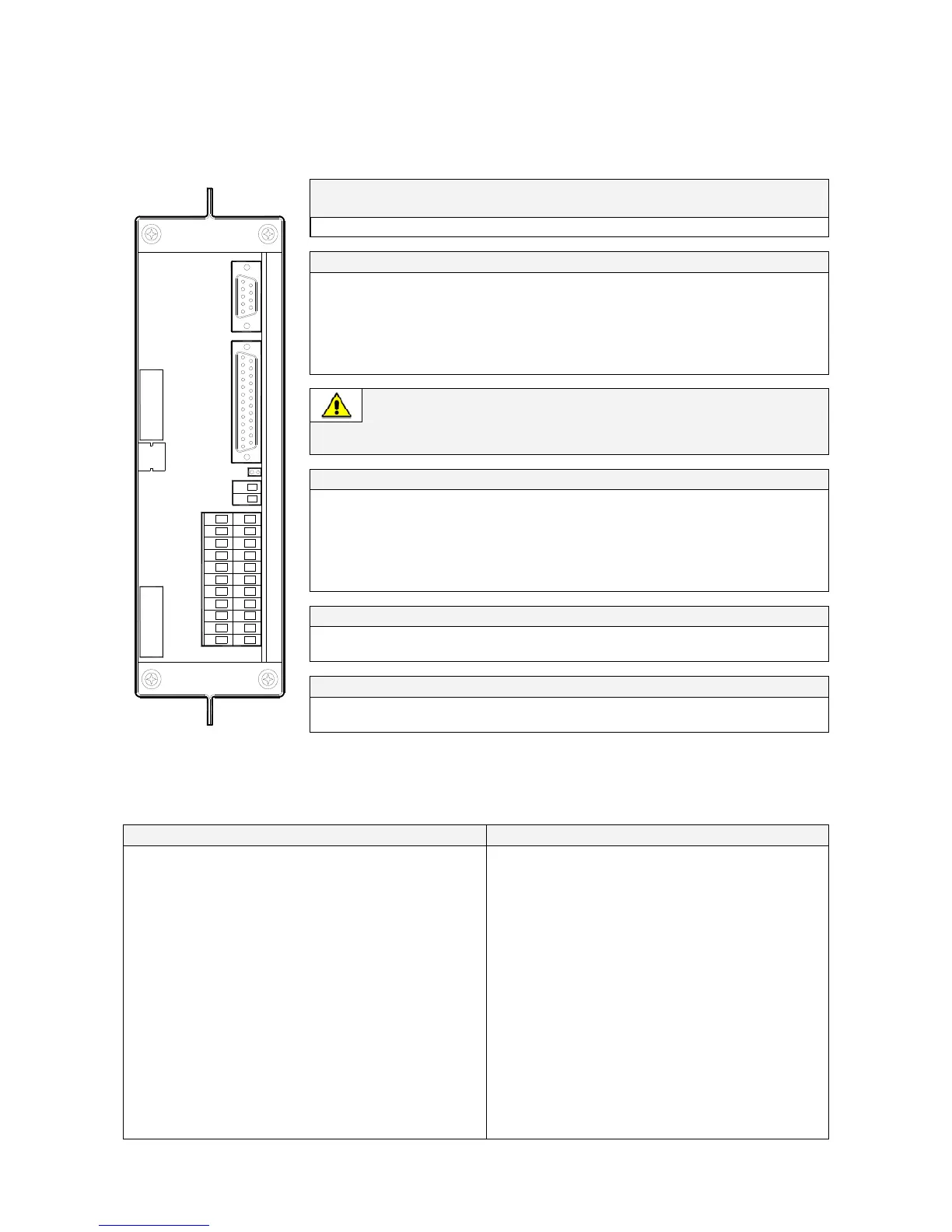
Serial port J3 - RS232 (sub D - female 9 pin)
Suitable for IMV protocol
Pin 2: TX (out) Pin 3: RX (in) Pin 5: GND
J2 (sub D-female 25p) – Output signals on voltage free contacts
J2 / 1, 2, 3
NO, C, NC Mains Failure (def. Parameter RL=1)
J2 / 4, 5, 6
NO, C, NC Load on Inverter (def. Parameter RL=3)
J2 / 7, 8, 9
NO, C, NC Stop Operation (def. Parameter RL=5)
J2 / 14, 15, 16
NO, C, NC Load on Mains (def. Parameter RL=2)
J2 / 17, 18, 19
NO, C, NC General Alarm (def. Parameter RL=4)
J2 / 20, 21, 22
NO, C, NC Acoustic Alarm (def. Parameter RL=6)
Signals on terminals X1 and on connector J2 are in parallel and therefore not
separated galvanically from each other.
The programmable signals on X1 and J2 will be disabled with Q1 open, with the
exception of the signals for “16 - Manual Bypass Q2 ON” and “26 - EPO”.
X1 terminals – Output signals on voltage free contacts
X1 / 1, 2, 3
NO, C, NC Mains Failure (def. Parameter RL=1)
X1 / 4, 5, 6
NO, C, NC Load on Inverter (def. Parameter RL=3)
X1 / 7, 8, 9
NO, C, NC Stop Operation (def. Parameter RL=5)
X1 / 12, 13, 14
NO, C, NC Load on Mains (def. Parameter RL=2)
X1 / 15, 16, 17
NO, C, NC General Alarm (def. Parameter RL=4)
X1 / 18, 19, 20
NO, C, NC Acoustic Alarm (def. Parameter RL=6)
X2 – Terminals for EPO (Emergency Power Off) connection
X2 / 1, 2 or J2 / 12, 25
NC EPO (Emergency Power Off)
Note: to enable this function, remove the Jumper JP3 on P4 – Customer Interface board.
Input contacts
X1 / 10, 21 or J2 / 10, 23
NO Programmable
X1 / 11, 22 or J2 / 11, 24
NO Programmable / Generator ON
SP_010-040_S7_customer interface_02
J2
J3
1
1
9
14
1
2
8
19 21 2220
10 119
17 181615
7654
12 1413
321
J3
J2
JP3
X2
X1
A
B
Fig. 9.1-1 Customer interface
NO = Normally Open C = Common NC = Normally Closed
The connectors A-J2 and B-J3 can be used for additional Advanced SNMP Card or an additional Custome
Interface (installation only when the UPS is switched Off).
Output signals on voltage-free contacts Programmable functions on input contacts
On terminals X1 or J2 connector, six of the following 27 signals
can be selected from the display, entering with the appropriate
password.
0- No Information
1- Buzzer
2- General Alarm
3- Load on Mains
4- Stop Operation
5- Load on Inverter
6- Mains Failure
7- DC Over Voltage
8- Low Battery
9- Overload
10- Overtemperature
11- Inverter-Mains not synchr.
12- Bypass Locked
13- Bypass Mains Failure
14- Rectifier Mains Failure
15- Battery Discharge
16- Manual Bypass Q2 ON
17- Rectifier ON
18- Inverter ON
19- Boost Charge
20- Battery Earth Fault
21- Battery Fault
22- Relay Input 1
23- Relay Input 2
24- Relay Output ON
25- Relay Output OFF
26- EPO
27- SEM Mode ON
Some UPS functions can be activated with
parameters when an external Normally Open (NO)
contact is closed on:
X1/10, 21 - J2/10, 23 or X1/11, 22 - J2/11, 24
Selectable functions by changing parameters
(password required) are:
0 - No function 1 - Inverter ON
2 - Inverter OFF 3 - Print All
4 - Status Relay 5 - Generator ON
6 - External Bypass ON
7 - External Battery Fuses, or External K3
(See Alarm 4104 - “Battery Fuses”)
Voltage free contacts: Max. DC / AC: 24V / 1.25A
IEC 60950 (SELV circuit)
Min. Signal Level: 5 Vdc/5 mA
 Loading...


