11
Read this operator’s manual and Important Safety Instructions before operating your generator.
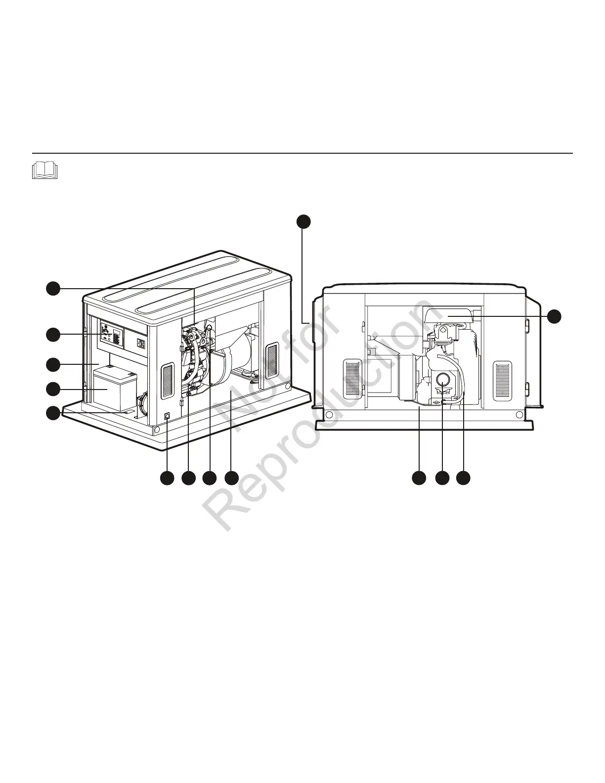
Compare the illustration with your generator to familiarize yourself with the locations of various
controls and adjustments. Save this manual for future reference.
Home Generator
Generator is shown with access covers removed for clarity.
A ‑ Oil Fill Cap—Removetoservicetheenginewith
recommended oil.
B ‑ Control Panel—Usedforvarioustest,operationand
maintenance functions. See System Control Panel.
C ‑ Control Panel Dooropening—Providesaccesstocontrol
panel and battery.
D ‑ Battery(installersupplied)—12VoltDC,valve-regulated,
rechargeable battery provides power to start the engine.
E ‑ ID Label(locatedonbase)—Identifiesunitbymodeland
serial number.
F ‑ Fuel Inlet—Fuelsupplyisconnectedhere.
G ‑ Engine Label—Identifiesenginemodelandtype.
H ‑ Oil Dip Stick—Usedtochecktheengineoillevel.
J ‑ Oil Fill Dooropening—Providesaccessforengineservicing.
K ‑ Oil Drain Dooropening—Providesaccessfor
engine servicing.
L ‑ Oil Filter—Filtersengineoiltoprolongsystemlife.
M ‑ Oil Drain Hose—Providedtofacilitateoilchanging.
N ‑ Air Cleaner —Protectsenginebyfilteringdustanddebris
out of intake air.
P ‑ Exhaust Port—High-performancemufflerlowersengine
noise to comply with most residential codes.
Controls
F G H J
K L M
P
N
A
D
B
E
C
 Loading...


