12
A
D
B
E
C
F
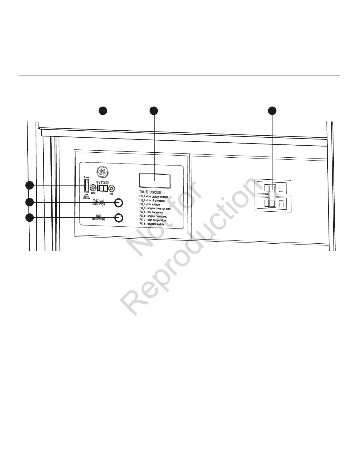
Compare this control panel illustration with your generator to familiarize yourself
with the location of these important controls:
System Control Panel
A ‑ SET EXERCISE—Usedtosettheexercisecyclestart
time and day-of-the-week. Exercise cycle only occurs in
AUTO mode.
B – MANUAL OVER‑RIDE—WithsystemswitchinAUTO
position, push the manual over-ride switch to start the
generator. To turn off the generator, push and hold the
manual over-ride switch again until engine stops.
C ‑ 15 Amp Fuse—ProtectsthehomegeneratorDCcontrol
circuits. If the fuse has ‘blown’ (melted open) or was
removed, the engine cannot crank or start. Replace the
fuse using only an identical ATO 15A fuse.
D ‑ System Switch—Thistwo-positionswitchisthemost
important control on the system and is used as follows:
•“AUTO” position is the normal operating position. If a
utility power outage is sensed, the system will start the
generator. When utility power is restored, AUTO lets
the engine stabilize internal temperatures, shuts off the
generator, and waits for the next utility power outage.
•“OFF” position turns off running generator, prevents
unit from starting and resets any detected faults.
E ‑ Digital Display—Displaysthetotalnumberofhours
the generator has been running and fault codes. Used
to schedule maintenance tasks and for troubleshooting
operational problems with the home generator. A
constant number displayed indicates the total hours of
operation. Fault conditions will flash “FC” followed by a
fault code number. All fault conditions are described in
Fault Detection System.
F ‑ Circuit Breaker —Protectsthegeneratorfromshortsand
other over-current conditions. Must be ON to supply power
to the automatic transfer switch.
 Loading...


