Open
Close
Internal Prelter
cavity
The Inlet Solenoid Valve (normally open) must be installed
as part of the water Inlet line and the Check Valve must be
installed as part of the water Outlet line. Refer to Steps 6 and
9 in section under
.
When the External Prelter housing needs to be removed for
servicing (e.g. to change the lter cartridge), close the Inlet
Valve and depressurize the External Prelter by draining the
water inside. To drain the water inside, open the Mini Ball
Valve at the bottom of the External Prelter housing. Depress
the red button on the External Filter head to speed up drain-
ing. A ¼” tubing can be inserted into the port of the Mini Ball
Valve to direct water into a drain or a large pail.
Note: Before installing or replacing the External Prelter
housing on the External Prelter head, inspect the O-ring
to ensure that it is in good condition. Lubricate the O-ring
sparingly with DOW CORNING 111 silicone lubricant.
1
6
3
5
4
2
Mount the Wall Bracket to the wall.
Attach the External Prelter head to the Wall
bracket using the four supplied lag bolts.
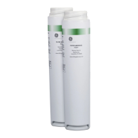
Remove the plastic wrap on the External Prelter
cartridge and insert the cartridge into the External
Prelter housing.
Ensure that the O-ring is seated at the lip of the
External Prelter housing. Screw the External
Prelter housing into the External Prelter head.
Tighten the connection with the Housing Wrench.
The plumbing must be compatible with the Inlet and
Outlet ports of the External Prelter.
If necessary, insert the supplied 1” x ¾” MNPT
adapters into the External Prelter ports and then
attach the External Prelter head to the plumbing.
Install the Mini Ball Valve with Plug at the bottom
of the External Prelter housing.
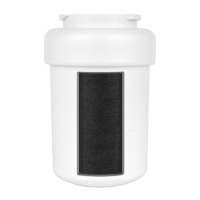
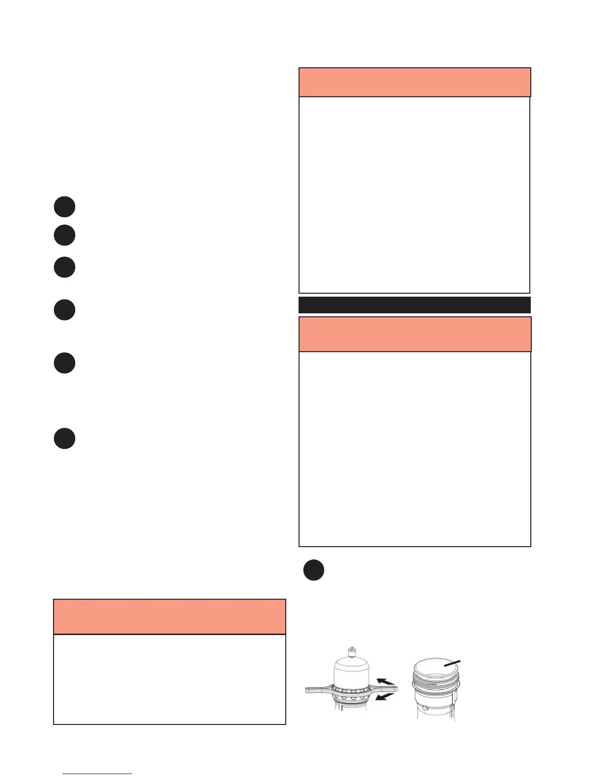
Remove the System Cap and remove the In-
ternal Prelter. Place the Internal Prelter in a clean, dry
area. Replace the System Cap and tighten using the Cap
Wrench.
For models with a Stainless Steel Prelter, a Carbon Pre-
lter may be purchased separately if desired.
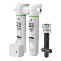
The Surface Water Option Kit is purchased separately from the
System, except for UF100 with optional Surface Water Option
Kit model. Install this kit in surface water applications.
For convenience of servicing, install the External Prelter
between the Inlet Valve and the Inlet Fitting Assembly.
1
In surface water applications, failure to install and/or
properly maintain the External Prelter cartridge
may cause premature fouling of the System and
therefore, shorten the System’s life or damage
the System membrane, causing personal injury and
/or death.
WARNING!
The System must be lled with water at all times once
commissioned. Failure to do so may cause System to
dry and become damaged, resulting in personal injury,
illness, and/or death.
Do not turn on any hot water taps when ushing the
System during commissioning or maintenance. If hot
water is used, high levels of factory preservative,
chlorine, or MC1 cleaning agent may enter the hot
water tank and may cause personal injury, illness,
and/or death.
Disposable protective gloves must be worn during
commissioning of the System to protect your hands. At
the end of the procedure, wash your hands thoroughly
with soap and water. Do not reuse gloves. Dispose of
gloves in the garbage.
WARNING!
If the System Cap is not properly tightened and/or the
O-ring is not clean, System leaks may occur. Leaks
may cause personal injury or property damage. Take
care not to cross-thread the System Cap during cap
installation. Ensure that the System Cap has at least
two full revolutions from where the threads rst engage
to where resistance is rst felt. Once resistance is felt,
use the Cap Wrench to turn the cap one more revolution
until the cap stops.
For UFC 207, UF 207, UFC 209, UF 209, UFC 211,
and UF 211 models, when the Internal Prelter is
removed, ensure the Thimble Filter remains in place,
seated in the spigot of the Prelter cavity. Removal of
the Thimble Filter may permit damage to the System
membrane, which may lead to illness or death.
WARNING!
18
 Loading...