Home
GE
Measuring Instruments
hydran m2
GE hydran m2 User Manual
5
of 1
of 1 rating
51 pages
Give review
Manual
Specs
To Next Page
To Next Page
To Previous Page
To Previous Page
Loading...
Hydran* M2 Insta
llation Guide
Page
26
16375 v9.0 Oct
12
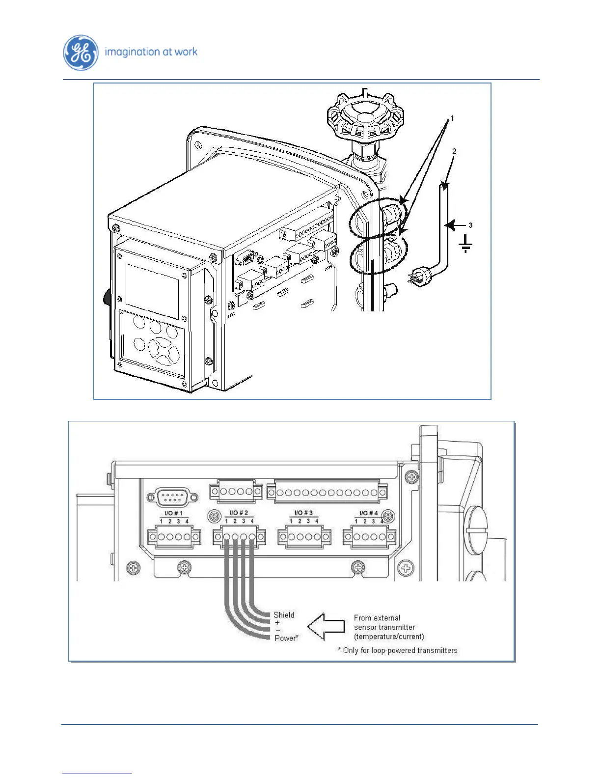
Figure
22
:
Ins
talling Cabl
e Conduits
Figure
23
:
Genera
l Wiring of the A
nalog Input Ter
minal Block
Note: This optional
Analo
g Input
board
c
an
be installed at any of
the four I/O locations.
1.
Mount
the
require
d, watert
ight conduits
fittin
gs:
½”
-
NPT, PG
-
13 o
r M20,
with
l
ock
nuts
and s
eali
ng
gask
ets
.
2.
Mount
r
equir
ed fle
xible co
ndu
its.
3.
Ground all
metallic
conduits
.
4.
Ensur
e
that
the plugs of all unused
openings are
secu
rely i
n pl
ace
.
25
27
Table of Contents
Default Chapter
2
Table of Contents
2
Introduction
5
Copyright Notice and Proprietary Rights
5
Trademark Notices
5
Customer Service
5
Safety Warnings in Six Languages
6
[EN] (in English) WARNINGS
6
[FR] (in French) ATTENTION
6
[ES] (in Spanish) ADVERTENCIA
6
[DE] (in German) WARNUNG
7
[IT] (in Italian) ATTENZIONE
7
[SV] (in Swedish) VARNING
8
Safety Symbols Description
8
Preface
9
Standard GE Energy Warranty
10
General Warnings
12
Figure 1: Plastic Cap Must Remain in Place until the Sensor Is Installed on the Valve
12
Figure 2: Do Not Touch the Sensor's Membrane with a Finger or an Object
12
Figure 3: Do Not Block the Sensor's Breathing Hole or Puncture the Breathing Hole's Membrane
13
Figure 4: Do Not Install the Hydran M2 at an Angle, Vertically or Using an Elbow
13
Figure 5: Do Not Install the Hydran M2 on an Elbow or a Fitting Box
13
Figure 6: Do Not Install the Hydran M2 on the Inlet Side of the Radiator Pump
14
Figure 7: Do Not Subject the Hydran M2 or Its Sensor to High-Pressure Water Streams
14
Figure 8: Do Not Paint the Sensor or Clean It with any Solvent
15
Installation
16
Overview
16
Figure 9: Typical Installation of the Hydran M2
16
Figure 10: Mounting Locations of the Hydran M2 on a Transformer
17
Figure 11: Bottom Clearance
18
Tools for Installation
19
Supplied with the Hydran M2
19
To be Supplied by the Installer
19
Figure 12: Tools Required for the Installation
20
Mounting the Hydran M2 on a Valve
21
Figure 13: Separating the Sensor from the Hydran M2
21
Figure 14: Disconnecting the Sensor Cable
21
Figure 15: Wrap the Sensor's Threads with PTFE Tape
22
Figure 16: Mount the Sensor Manually Onto the Valve and Tighten It, Using an Adjustable Wrench
22
Figure 17: the Bleed Screw Must be on Top, at the 12 O'clock Position
23
Figure 18: Opening the Valve and Purging the Air from the Sensor
23
Figure 19: Installing the Hydran M2 on the Sensor
24
Figure 20: Grounding the Hydran M2 Enclosure
24
Installing the Cables
25
Figure 21: Removing the Hydran M2 Cover
25
Figure 22: Installing Cable Conduits
26
Figure 23: General Wiring of the Analog Input Terminal Block
26
Figure 24: Wiring of Self-Powered, Analog Inputs
27
Figure 25: Wiring of Two-Wire, Loop-Powered, Analog Inputs
27
Figure 26: Wiring of Three-Wire, Loop-Powered, Analog Inputs
27
Figure 27: General Wiring of the Analog Output Terminal Block
28
Figure 28: Wiring of the 4-20 Ma Analog Output Terminal Block
28
Figure 29: Wiring of the 0-1 Ma Analog Output Terminal Block
28
Figure 30: Wiring of the Alarm Relays Terminal Block
29
Figure 31: Wiring of the AC Power Supply Terminal Block
29
Software Configuration
30
User Interface Overview
30
Figure 32: User Interface Overview
30
Figure 33: Display Overview
30
Setting the Date and Time
31
Testing the Sensor
32
Setting Gas Level Alarm Parameters
33
Setting Moisture Level Alarm Parameters
35
Setting the Network Communication Parameters
36
Setting the Optional Analog Input Parameters
38
Setting the Optional Analog Output Parameters
41
Configuring the Models
42
Installing the Cover
43
Figure 34: Installing the Cover
43
Commissioning
44
Figure 35: Wait 24 Hours
44
Figure 36: Compare the Gas Level Reading to a Recent DGA
44
Communications & Networking
45
Forming a Local Network of Hydran M2S
45
Figure 37: Network Overview (Daisy Chaining of Hydran M2S)
45
Figure 38: Local Communications with a Laptop Computer (for Service Only)
45
Figure 39: Grounding the RS-485 Conduits
46
Figure 40: General Wiring of the RS-485 Terminal Block
46
Figure 41: Wiring Details of the RS-485 between 2 or more Hydran M2S
47
Connecting the Hydran M2 to Hydran 201Ci Controllers
48
Figure 42: Remote Communications with a Host Computer Via a Modem
48
Figure 43: Wiring of the Supervisory Link between a Hydran M2 and a Hydran 201Ci-1 Controller
49
Figure 44: Wiring of the Supervisory Link between a Hydran M2 and a Hydran 201Ci-C Controller
49
Connecting the Hydran M2 to a D25
50
Figure 45: Wiring of the Supervisory Link between a Hydran M2 and a Hydran 201Ci-4 Controller
50
Figure 46: Wiring of the RS-485 Link between a Hydran M2 and a D25
50
Modification Record
51
5
Based on 1 rating
Ask a question
Give review
Questions and Answers:
Need help?
Do you have a question about the GE hydran m2 and is the answer not in the manual?
Ask a question
GE hydran m2 Specifications
General
Brand
GE
Model
hydran m2
Category
Measuring Instruments
Language
English
Related product manuals
GE Hydran M2-X
204 pages
GE Hydran 201i
266 pages
GE XDP-H2
96 pages
Baker Hughes PanaFlow LC XMT1000
190 pages
GE MAC VU360
168 pages
GE TransPort
30 pages
GE AB Series
12 pages
GE Kelman DGA900
92 pages
GE Sievers 500 RL
186 pages
GE TransPort PT900
190 pages
GE Transport PT878
297 pages
GE DINAMAP ProCare
134 pages

 Loading...


