3.4 APPLICATION NOTES
3.4.1 PARALLEL FEEDERS
E00603
33 kV
R
1
OC/EF
R2
OC/EF
R3
DOC/DEF
OC/EF
R4
DOC/DEF
OC/EF
11 kV
R5
OC/EF
Loads
SBEF
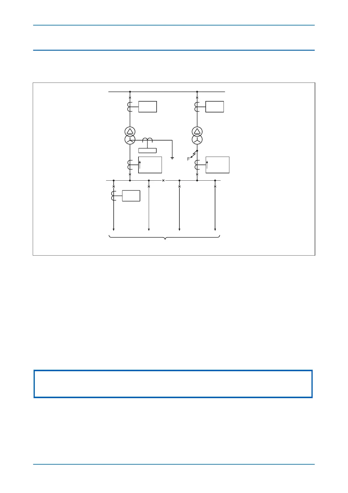
Figure 36: Typical distribution system using parallel transformers
In the application shown in the diagram, a fault at ‘F’ could result in the operation of both R3 and R4 r
esulting in
the loss of supply to the 11 kV busbar. Hence, with this system configuration, it is necessary to apply directional
protection devices at these locations set to 'look into' their respective transformers. These devices should co-
ordinate with the non-directional devices, R1 and R2, to ensure discriminative operation during such fault
conditions.
In such an application, R3 and R4 may commonly require non-directional overcurrent protection elements to
provide protection to the 11 kV busbar, in addition to providing a back-up function to the overcurrent devices on
the outgoing feeders (R5).
For this application, stage 1 of the R3 and R4 overcurrent protection would be set to non-directional and time
graded with R5, using an appropriate time delay characteristic. Stage 2 could then be set to directional (looking
back into the transformer) and also have a characteristic which provides correct co-ordination with R1 and R2.
Directionality for each of the applicable overcurrent stages can be set in the directionality cells (I>1 Direction).
Note:
The principles outlined for the parallel transformer application are equally applicable for plain feeders that are operating in
parallel.
Chapter 6 - Current Protection Functions P14x
102 P14xEd1-TM-EN-1
 Loading...


