V00903
Φ
q
c
V
A
I
AS
I
AS
C
V
A
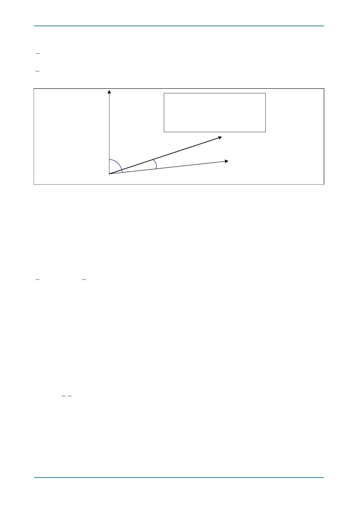
= A-phase-N volts
I
A
S
= A-phase sensitive current
I
ASC
= compensated a phase sensitive current
Φ = angle of I
AS
with respect to V
A
q
c
= CT correction angle
Figure 140: Sensitive Power input vectors
CT Compensation
The CT correction r
otates the I
AS
vector by the correction angle. This correction is performed before the power
calculation and can be achieved with the use of a rotation matrix:
cos sin
sin cos
θ θ
θ θ
C C
C C
−
The corrected phase-A sensitive current I
ASC
is therefore:
I
I
I
I
I
I
ASC
ASCr
ASCi
AS
ASr
ASi
C C
C
=
= =
−cos sin
sin co
θ θ
θ
ss
cos sin
sin cos
θ
θ θ
θ θ
C
ASr C ASi C
ASr C ASi C
I I
I I
=
−
+
therefore:
I I I
ASCr ASr C ASi C
= −cos sin
θ θ
and
I I I
ASCi ASr C ASi C
= +sin cos
θ θ
Active Power Calculation
The compensated A-phase sensitive curr
ent vector is used to calculate the sensitive A-Phase active power P
AS
.
Using the equation:
we can derive:
P V jV I jI
AS Ar Ai ASCr ASCi
= +
( )
+
( )
Re
= +
( )
−
( )
= +
( )
+Re ReV jV I jI V I V I j V I
Ar Ai ASCr ASCi Ar ASCr Ai ASCi Ai ASCrr Ar ASCi
V I−
( )
Chapter 12 - Power Protection Functions P14x
268 P14xEd1-TM-EN-1
 Loading...


