369 MOTOR MANAGEMENT RELAY – QUICKSTART GUIDE 2–5
369 Motor Management Relay
Chapter 2: Installation
GE Consumer & Industrial
Multilin
Instal lation
2.1 Mechanical Installation
2.1.1 Mechanical Installation
The 369 is contained in a compact plastic housing with the keypad, display,
communication port, and indicators/targets on the front panel. The unit should be
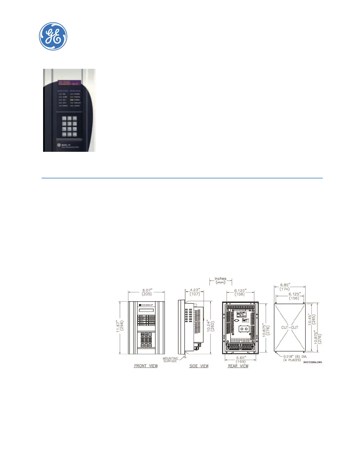
positioned so the display and keypad are accessible. To mount the relay, make cutout and
drill mounting holes as shown below. Mounting hardware (bolts and washers) is provided
with the relay. Although the relay is internally shielded to minimize noise pickup and
interference, it should be mounted away from high current conductors or sources of
strong magnetic fields.
FIGURE 2–1: Physical Dimensions
 Loading...


