Service Manual
R8010RB
MVAX Page 7/24
2.6 MVAX 21, 31, 91
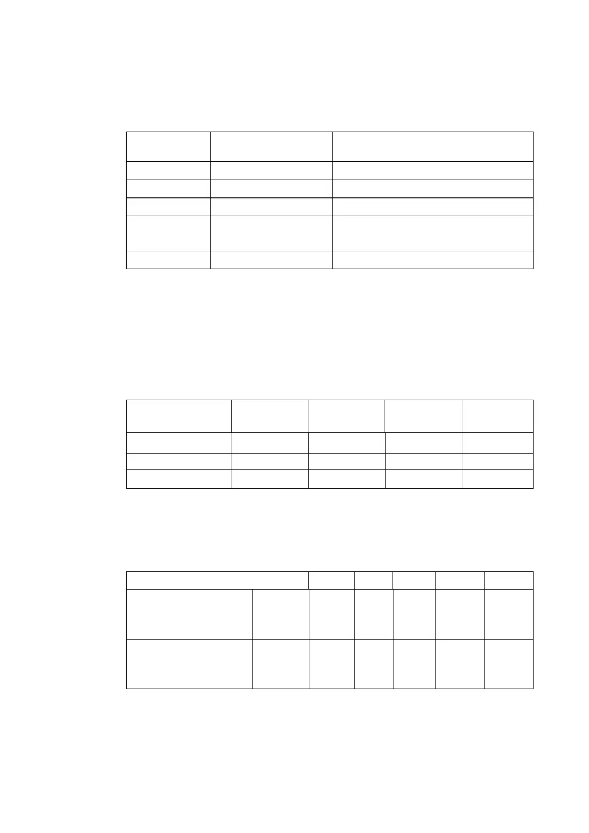
For MVAX 21, 31 and 91 relays, check the external wiring to ensu
re the correct values of
external resistors (where appropriate) are wired to the correct relay terminals, in accordance
with the following table and the appropriate application diagram.
Supply volts
Alarm supply circuit
R
EXT
1
Trip supply circuit
R
EXT
2 and R
EXT
3, as appropriate
24/27 - 270 ohm
30/34 – 470 ohm
48/54 240 ohm 1,500 ohm
110/125 1,500 ohm 4,000 ohm
*1,200 ohm
220/250 4,100 ohm 2 off 4,000 ohm in series
* S/R reverse flag
2.7 Electrical operation tests
2.7.1 MVAX 11 only
Isolate the MVAX from the trip supply batteries by removing fuses/links as necessary.
Connect a supply across relay terminals 21 – 27 an
d supply the relevant voltage from the list
below. Check that the current is within those figures stated in the same column. Repeat
again only using terminals 27 – 28.
Rated voltage range (V) 30/34 48/54 110/125 120/250
Test voltage (V) 30 48 110 220
Terminals 21 – 27 46.1/56.3mA 24.1/29.5mA 11/13.4mA 11.4/14mA
Terminals 27 – 28 46.1/56.3mA 24.1/29.5mA 11/13.4mA 11.4/14mA
2.7.2 MVAX 12 only
Isolate the relay from the trip supply batteries by removing fuses/links as necessary.
Using an ohmmeter check the resistance across the rel
ay side of the fuses/links. Provided
there are no parallel paths, the resistance should be within ±10% of the following:
MVAX 12 rating range (V)
24/27 30/34 48/54 110/125 220/250
Relay resistance (Ohms):
No flag/hand reset flag
2
contacts
4
contacts
710 416 1170
620
2970
1760
10370
7470
33100
23100
Relay resistance (Ohms):
No flag/hand reverse flag
2
contacts
4
contacts
590 407 940
590
2330
1740
8670
6770
27100
22100
Connect a variable dc supply to the isolated circuit ensuring correct polarity is observed
(Terminal 13 of the relay must be maintained POSITIVE).
 Loading...


