Service Manual
R8010RB
MVAX Page 13/24
3. MAINTENANCE
Periodic maintenance is not necessary. However, periodic inspection and test is
recommended. This should be carried out every 12 months or more often if the relay is
operated frequently or is mounted in poor environmental conditions.
Tests 2.3, 2.4, 2.5, 2,6 and 2.7 should be
carried out to prove operation
.
4. MECHANICAL SETTINGS
4.1 General
Armature gap measurements should be made with the top of the feeler gauge level with the
centre line of the core.
Contact pressures are measured with a gramme gau
ge at the contact tips.
In general contact gaps and follow through are defined
by quoting an armature gap at which
the tips should be just closed or just open.
The relay contact state is always defined with the relay in the unene
rgised position, unless
otherwise specified on the appropriate circuit diagram.
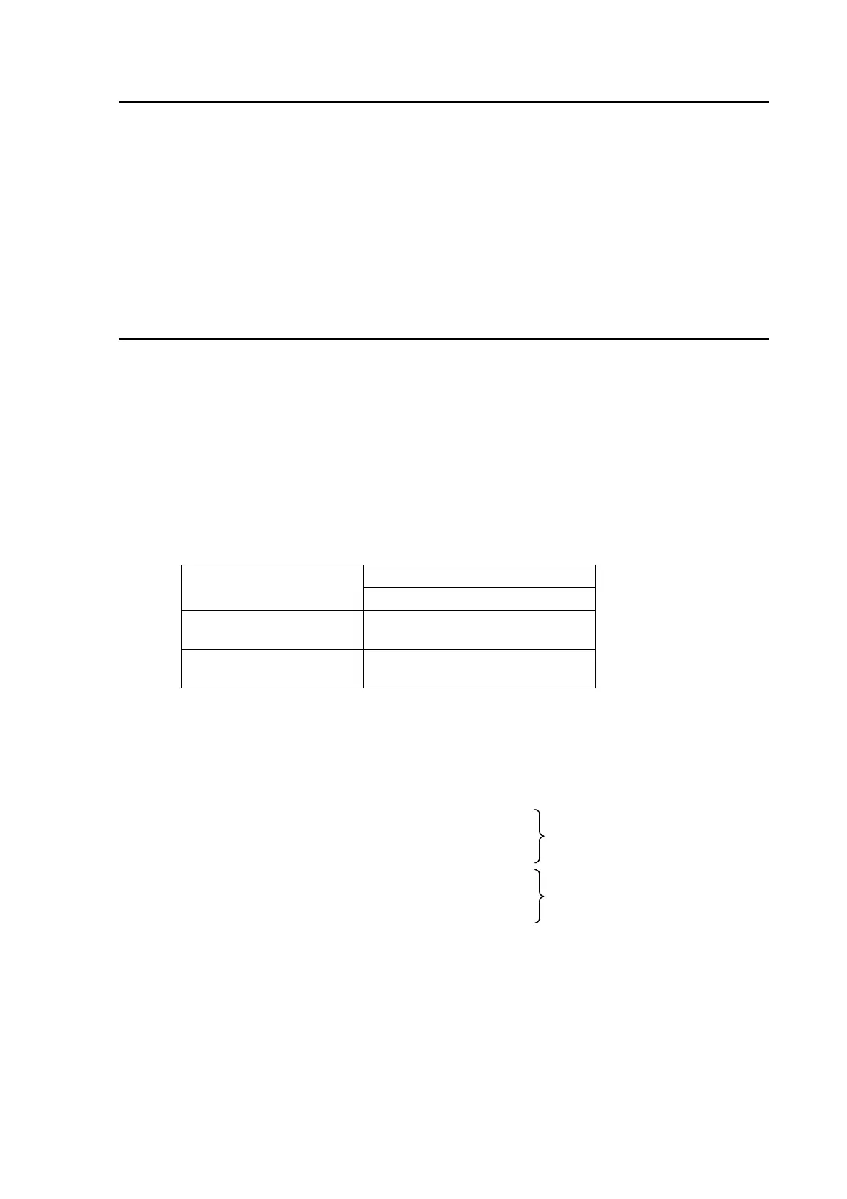
Symbol used on diagrams
Contact Type
Normal duty
Make
(Normally open)
M
Break
(Normally closed)
B
4.1.1 With the armature closed the clearance between the back of the armature and the back stop
should be 0.075/0.2mm (0.003"/0.008").
4.1.2 Nominal armature gap open.
MVAX 11
Unit RL
1
1.38mm (0.055")
MVAX 12
MVAX 21, 31 and 91
Unit RL
1
1.5mm (0.060")
MVAX 21
Unit RL
2
MVAX 31, 91
Unit RL
2
and RL
3
0.7mm (0.030")
Note: On the MVAX 12 a screw is fitted to the armature.
It must protrude by 0.075/0.2mm (0.003"/0.008").
 Loading...


