2–1 X-ray System
See Illustration 1–2.
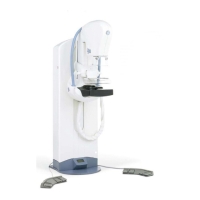
The x-ray system is equipped with a Telescopic Column which supports the Examination
Arm.
The Telescopic Column must be secured to the floor using the fixed baseplate.
98, & '
4
'# #
&#, *( (!
'(:9( (
.8*(( 5
4(*(( 5
2;# " .8*(( 5 4(8*(( 5 <(! =
* * (#
9>! (#
+ (# " *
This consists of two arms (1. Tube-Support Arm, and 2. Receptor-Support Arm) which are
connected to the Telescopic Column by a common rotating shaft. The Positioning Arm can
be rotated through 360 degrees (+180/–180 degrees) about this shaft.
This couples the Positioning Arm to the Telescopic Column. The silk-screened markings
indicate the angles of tilt.
Consists of two cylinders: 1. a fixed cylinder, and 2. a telescoping cylinder which elevates
the Positioning Arm. A readout, located on top of the Telescopic Column, indicates:
D Magnification factor,
D Compression force and compressed breast thickness
D Field size,
D Tube–Support Arm angle. Angle is displayed when pressing the brake release button.
After releasing the brake button, angle remains displayed for 2 seconds before to come
back to default display (compression force, breast thickness....).
Two Emergency Stop pushbuttons are located, one on either side of the Telescopic Column.
Note: If the Telescopic Column touches an obstacle during Down-movement, the
movement is inhibited.
!
"#
#
FOR TRAINING PURPOSES ONLY!
NOTE: Once downloaded, this document is UNCONTROLLED, and therefore may not be the latest revision. Always confirm revision status against a validated source (ie CDL).

 Loading...