47
Chapter 4. Maintenance and Peripherals
4.1. Maintenance and Examination
Frequent examination and maintenance is not required for VAT20.
To maintain appropriate reliability for a long term of time, please proceed with following periodical
examination. Remember to turn off power supply and wait till the Power LED went off before
proceed. (Due to the large amount of remaining charges in the internal capacitors.)
(1) Clean out internal dust and dirt.
(2) Check out mounting screws on every terminal and parts. Tighten loose screws.
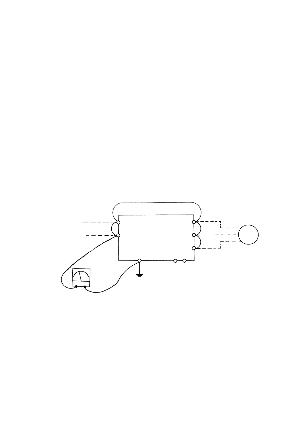
(3) Dielectric strength test
(a) Remove all conducting wires between VAT20 and outside world. Power must be turned OFF.
(b) The dielectric strength test inside VAT20 should be carried out only for VAT20 major circuitry.
Use DC 500V: high resistance meter. Measured resistance should be higher than 100M ohm.
CAUTION: Do not perform dielectric strength test to the control circuit.
Connection for dielectric strength test
Input power source
DC-500V
high-resistance
Earth terminal
Motor
L1 (R) T1 (U)
L2 (S) VAT20 T2 (V)
T3 (W)
 Loading...


