■
GE Zenith Controls 21
■
MX150 Operation and Maintenance Manual (70R-2000)
Standard Transition
Each MX150 microprocessor based ATS controller
requires a relay/transformer box to apply line voltage
to the ATS operator via coil control relays. Also required
is power for the MX150 printed circuit board and an
application of sensing voltage proportional to line voltage.
This is accomplished by the relay transformer box. This
method of switching operator voltage and applying power
and sensing voltage to the printed circuit board isolates
R/T Box Primary 1 VA 25 VA
Assembly Voltage XFMR XFMR
Part No. at 50/60 Hz Part No. Part No.
57P-1115 120V K-3216 K-3224
57P-1116 208-220V K-3217 K-3225
57P-1117 230-240V K-3218 K-3226
57P-1118 277V K-3219 K-3227
57P-1119 380-400V K-3220 K-3228
57P-1120 416-440V K-3221 K-3229
57P-1121 460-480V K-3222 K-3230
57P-1122 575-600V K-3223 K-3231
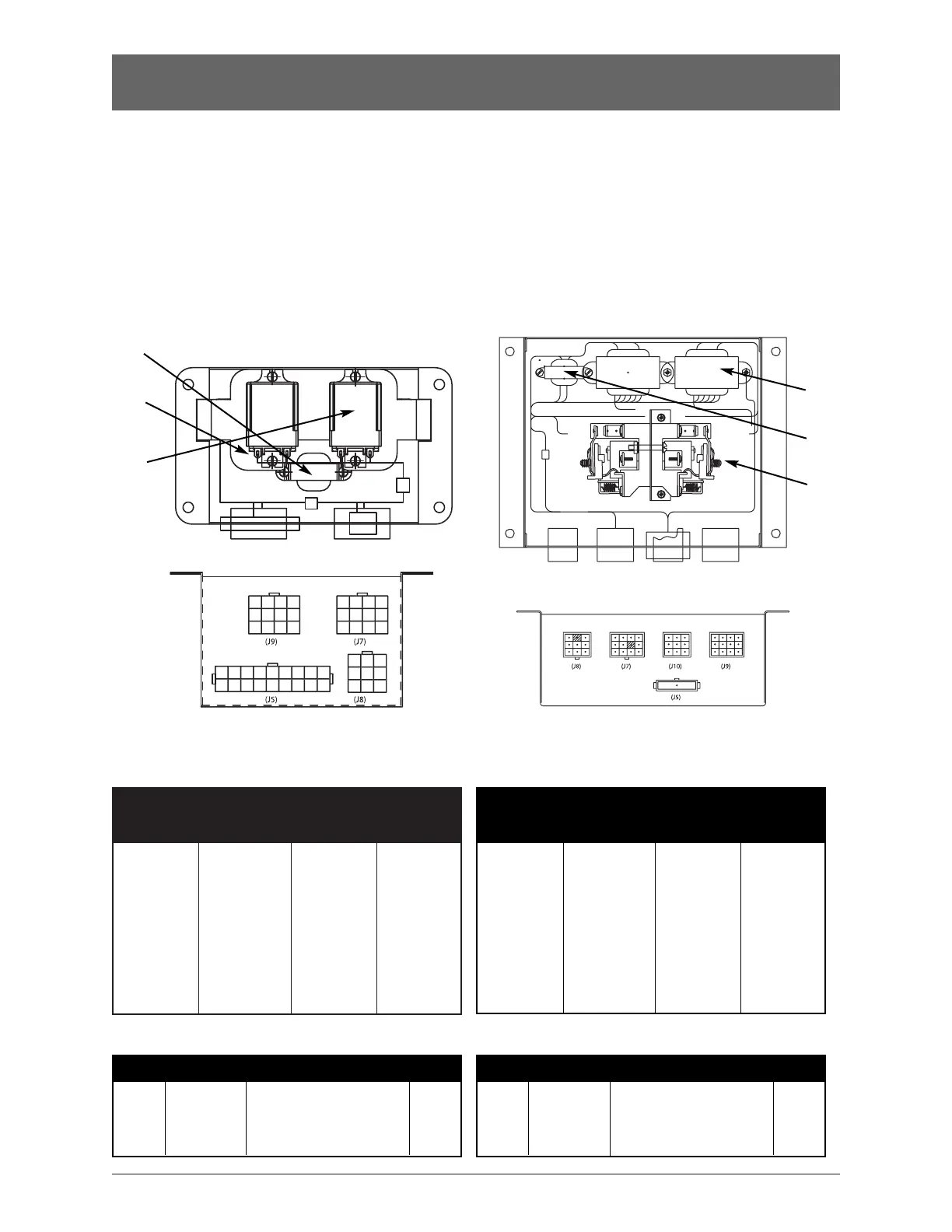
Relay/Transformer (R/T Box)
40-225 Amp Molded Power Section
Transformer Usage (see Figure 10)
Item Part No. Description Qty
1 See Chart Transformer (1 VA) 1
2 See Chart Transformer (25 VA) 2
3 K-1274 Relay Flange Mounted 2
Bill of Material
R/T Box Primary 1 VA 25 VA
Assembly Voltage XFMR XFMR
Part No. at 50/60 Hz Part No. Part No.
50P-1005 120V K-3216 K-3224
50P-1006 208-220V K-3217 K-3225
50P-1007 230-240V K-3218 K-3226
50P-1008 277V K-3219 K-3227
50P-1009 380-400V K-3220 K-3228
50P-1010 416-440V K-3221 K-3229
50P-1011 460-480V K-3222 K-3230
50P-1012 575-600V K-3223 K-3231
40-3000 Amp - All Other Standard Types
Transformer Usage (see Figure 11)
Item Part No. Description Qty
1 See Chart Transformer (25 VA) 2
2 See Chart Transformer (1 VA) 1
3 K-1260 Coil Control Relay (24V) 2
Bill of Material
the MX150 from the line voltage, further protecting
the controller from harmful line transients. Two versions
of the R/T box exist depending on the type of ATS
(standard transition or delayed transition).
The following layout drawings of the R/T Box compo-
nents (standard and delayed transition) include a bill of
materials for replacement parts. Schematics are included
to indicate proper wiring.
1
2
(inside)
3
1
2
3

 Loading...