■
4 GE Zenith Controls
■
MX150 Operation and Maintenance Manual (70R-2000)
Installation
(cont’d)
Engine Start
Control Connections
The engine-start terminals are clearly identified by a
label on the microcontroller backplate. In the case of
manual transfer switches, or in other applications not
requiring the microprocessor, clearly marked terminal
blocks are provided in the upper left corner of the con-
trol panel for the engine start control wires.
Terminals for field connections to the A3 Emergency
auxiliary contacts and the A4 Normal auxiliary contacts
are also provided. These terminals are clearly marked
and appear on the side of the power panel. On 400
amp metal frame units these terminals appear on the
bracket above the operator handle.
Initial Energization
Before proceeding, refer to the information package
supplied with the ATS and read and understand the
information on all accessories provided.
1. Unlock the enclosure.
2. Open the enclosure.
3. Verify the correct system voltage.
NOTE: The equipment rating nameplate on
the transfer switch lists the voltage.
See
Figure 3
.
4. Close Source 1 circuit. breaker.
NOTE
:The controller will illuminate Source 1
Available LED if proper voltage
is sensed.
5. Verify the phase to phase voltages at the Normal
line terminals.
6. Close the Emergency source circuit breaker.
7. Start the generator’s engine.
DANGER
HAZARDOUS VOLTAGE
(Can Cause Severe Injury or Death)
Turn OFF all power before installation, adjustment, or removal of transfer switch or any of its components.
NOTE: The controller will illuminate Source 2
Available LED when preset voltage
and frequency levels are reached.
8. Verify the phase to phase voltages at Source 1
line terminals.
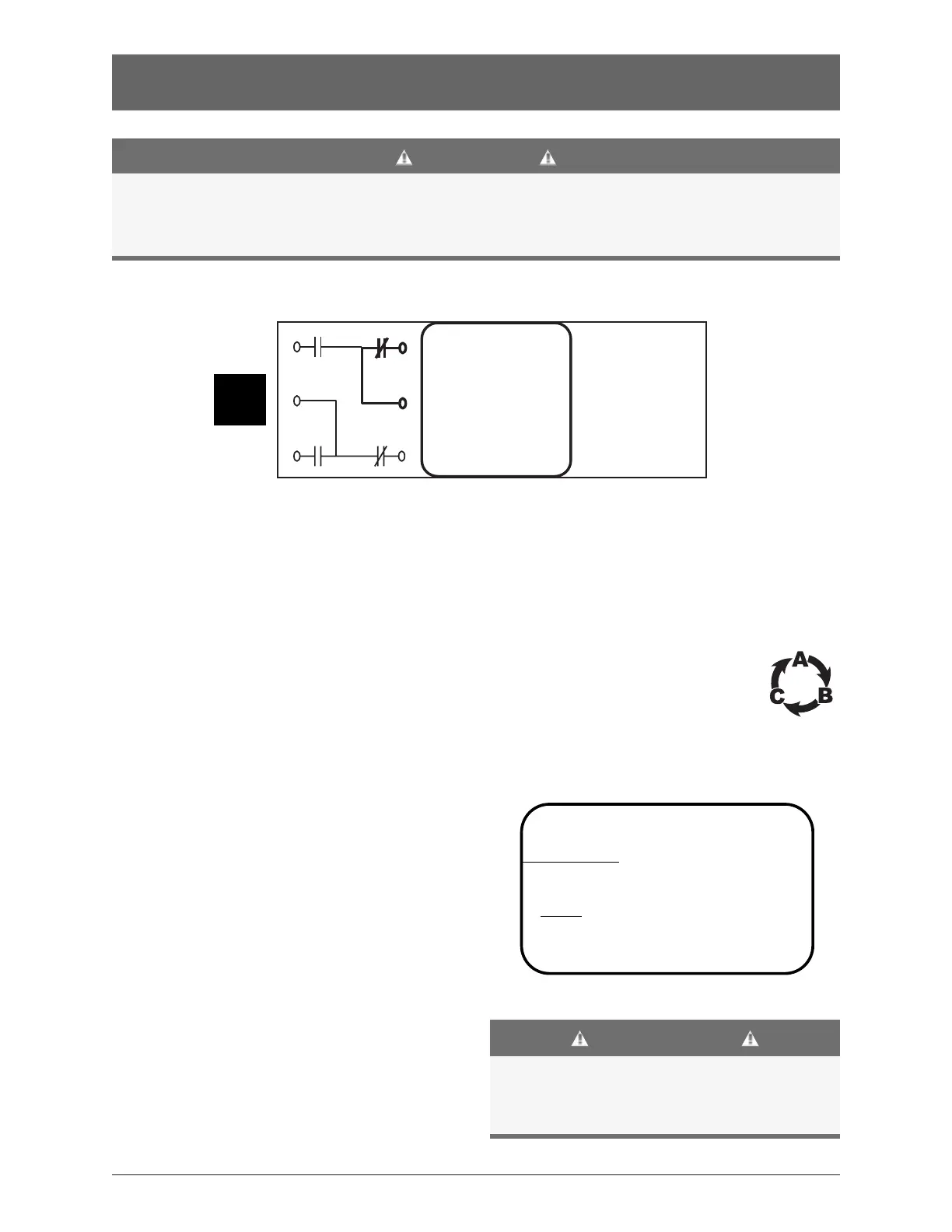
9. Verify that the phase rotation of Source 1
is the same as the phase rotation of
Source 2.
10. Shut down the generator’s engine.
11. Place the starting control in the Automatic position.
12. Complete the visual inspection of the transfer switch.
13. Close the enclosure.
14. Lock the enclosure.
CAUTIONS
Certain accessories, per specific
schematics, can inhibit automatic transfer.
Engine Gen-Set could start when
engine control wires are attached.
Figure 4
g
SERIAL NUMBER:
RA
TING: VOLTS -
AMPS -
SYSTEM VOLTS:
MODEL NUMBER:
HZ -
PHASE -
GE Zenith Controls

 Loading...