• Out
• InP
Lo.S ... Hi.S
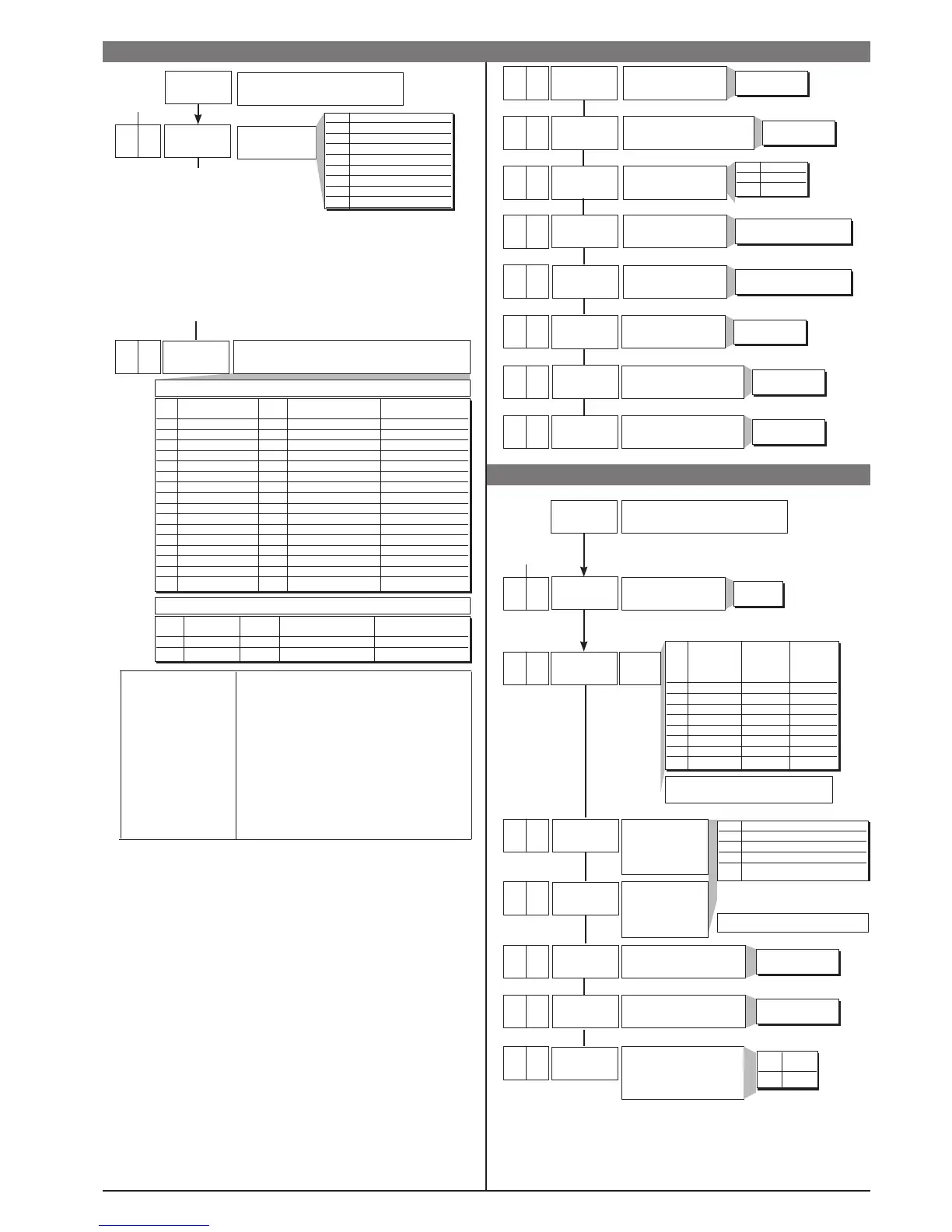
Type of probe, signal and scale of main input
tYP Type of probe Scale Max. scale range Max. scale range
(C/F) without decimal point with decimal point
0 J (Fe-CuNi) C 0 / 1000 0,0 / 999,9
1 J (Fe-CuNi) F 32 / 1832 32,0 / 999,9
2 K (NiCr-Ni) C 0 / 1300 0,0 / 999,9
3 K (NiCr-Ni) F 32 / 2372 32,0 / 999,9
4 R (Pt13Rh - Pt) C 0 / 1750 0,0 / 999,9
5 R (Pt13Rh - Pt) F 32 / 3182 32,0 / 999,9
6 S (Pt10Rh - Pt) C 0 / 1750 0,0 / 999,9
7 S (Pt10Rh - Pt) F 32 / 3182 32,0 / 999,9
8 T (Cu-CuNi) C -200 / 400 -199,9 / 400,0
9 T (Cu-CuNi) F -328 / 752 -199,9 / 752,0
10 B (Pt30Rh - Pt6Rh) C 44 / 1800 44,0 / 999,9
11 B (Pt30Rh - Pt6Rh) F 111 / 3272 111,0 / 999,9
12 E (NiCr-CuNi) C -100 / 750 -100,0 / 750,0
13 E (NiCr-CuNi) F -148 / 1382 -148,0 / 999,9
14 N (NiCrSi-NiSi) C 0 / 1300 0,0 / 999,9
15 N (NiCrSi-NiSi) F 32 / 2372 32,0 / 999,9
tYP Type of probe Scale Max. scale range Max. scale range
(C/F) without decimal point with decimal point
16 PT100 C -200 / 850 -199,9 / 850,0
17 PT100 F -328 / 1562 -199,9 / 999,9
SENSOR: RTD 3 wires
InP
Main input offset
correction
Lower limit for local setpoint
and absolute alarms
SENSOR: TC
-999 ... 999
scale points
Lo.S ... Hi.S
Upper limit for local setpoint
and absolute alarms
0
0
1000
0
0
1000
22
Default Custom
Configuraz.
Out
Output settings
+ 8 to disable on power-up until first alarm
AI.t Direct Absolute Normal
(maximum) Relative Symmetrical
Inverse to active (window)
(minimum) setpoint
0 direct absolute normal
1 inverse absolute normal
2 direct relativo normal
3 inverse relativo normal
4 direct absolute symmetrical
5 inverse absolute symmetrical
6 direct relativo symmetrical
7 inverse relativo symmetrical
0 ..1
Number of
alarms
Alarm
type
1
Default Custom
Configuraz.
0
+16 disable parameters
CFG: rst, PrE, SoF, Lbt, Lbp, FAP,
InP: FLt, FLd, oFS, LoL, HIL
Out: ALn, rEL
FLt, FLd, Lbp, HIL stay at set value.
ALn is forced to 1
All other parameters are considered 0
Default: derived action sample time = 1 sec
+32: derived action sample time = 8sec
+64: derived action sample time = 240msec with derived action filter assigned
to Flt parameter (time filter)
0.1
0.5
0
Max. non-linearity error
for thermocouples (TC),
resistors (PT100)
The error is calculated
as deviation from
theoretical value
and is expressed as
percentage of full scale
(°C)
S, R range 0...1750°C; error < 0.2% f.s. (t > 300°C) / for
other range; error < 0.5% f.s.
T error < 0.2% f.s. (t > -150°C)
B range 44...1800°C; error < 0.5% f.s. (t > 400°C)
Tc: J, K, E, N, error < 0,2% f.s.
error < 0,2% f.s.
PT100 scale -200...850°C
Precision better than 0,2% f.s. at 25°C.
(tr
tyP
FLt
FLd
dP.S
Lo.S
XI.s
oFS
Lo.L
xI.L
AL.n
AI.t
Fault action (definition of state
in case of broken sensor)
alarms AL.
Select intrinsic safety.
1) In case of broken sensor, the logic state of the alarm assumes the selected logic value
without considering alarm type (direct or inverse): ON = alarm ON, OFF = alarm OFF
2) The alarm is assigned to available outputs by setting codes r.o.1, r.o.2.
rEL Alarm
0 OFF
1 ON
Cycle time OUT1 relay or
logic = HEAT or COOL
Cycle time OUT2 relay or
logic = HEAT or COOL
1. ... 200 sec
1. ... 200 sec
0
10
10
OUT 1
Attribution of
reference
signal:
HEAT, COOL, AL
+ 16 for logic level denied at output
OUT 2
Attribution of
reference
signal:
HEAT, COOL, AL
r.o.x Output function
0 HEAT (heating control output)
1 COOL (cooling control output)
2 AL - alarm
6 LBA - allrm LBA
2
0
(t.1
(t.2
rEL.
r.o.1
r.o.2
Input settings
Type of control
[0...91]
CtrL Type of control
0 P hot
1 P cold
3 PI hot
4 PI cold
6 PID hot
7 PID cold
9 ON-OFF hot
10 ON-OFF cold
Digital filter
on main input
Digital filter on display of
process variable; acts as
hysteresis
Decimal point position for
main input scale
0,0 ... 20,0 sec
0 ... 9,9
scale points
dP.S Format
0 xxxx
1 xxx.x
Minimum limit of main
input scale
min…max scale of input
selected in tyP
Maximum limit of main
input scale
min…max scale of input
selected in tyP
3
2
0,1
0,5
0
0
1000
0
6
1000
1
1
0
2
30
10
1
 Loading...


