1 • PRELIMINARY INSTRUCTIONS
This section contains information and warnings
of a general nature which should be read
before proceeding with controller installation,
configuration and use.
General Description
The series 450 temperature controller, measuring
48x48mm (1/16 DIN), offers simplicity of use and high
quality of control.
The input from temperature sensors is “universal”
and configurable with type J, K, R, S, T, B, E,
N thermocouples and with 3-wire Rt100 resistance
thermometers.
The user interface has a complete double display with
green LEDs, 4 keys, and two red LEDs to signal active
outputs.
The Lexan® membrane on the front panel guarantees
an IP65 protection level for these products.
The controller outputs, freely configurable as control
output and alarm output, are available in a 5A/250VAC
relay version or in a logic signal version to drive solid
state relays.
The input signal read speed (120msec) and the tested
PID control algorithm with selftuning and autotuning
parameter functions guarantee accurate and stable
control even for rapid and discontinuous heating
systems.
Series 450 models are factory-configured to satisfy
most industrial heating applications (input for probe J,
hot PID setting, 10 second cycle time) and can always
be modified from keyboard and from PC with a few
parameters grouped on intuitive menus.
A programming kit for PC is available, consisting of
a cable and a user-friendly program for Windows
with Wizard pages, oscilloscope for process analysis,
saving of parameter recipes, and ability to reset factory
parameters. A settable software protection code
(password-protected) lets you limit access to internal
parameters to various levels, up to total protection.
Electrical Interface
All connection terminals (power supply, inputs, outputs,
options) are grouped together on the back of the
instrument.
For technical specifications and performance details refer
to Section 13 “Technical Specifications”.
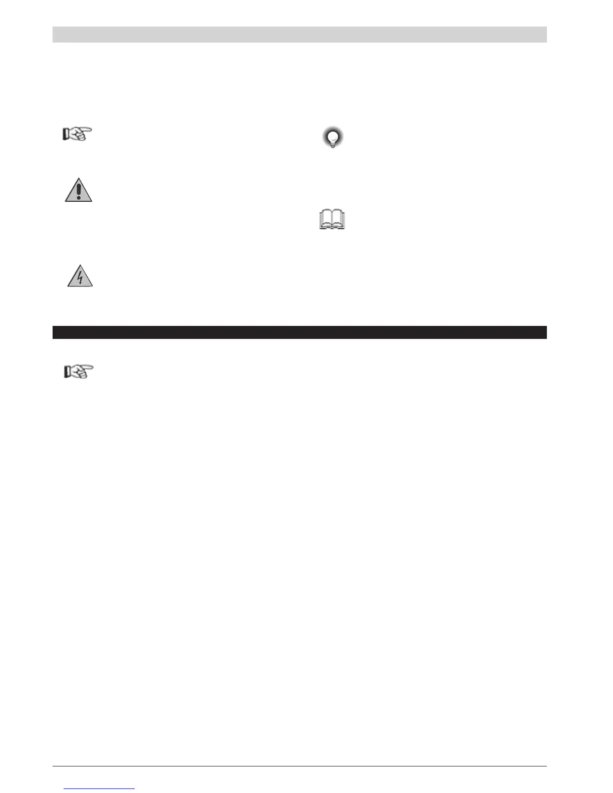
Graphic symbols used
To distinguish between the type and importance of the information provided in these instructions for use, graphic
symbols have been used as a reference to make interpreting the information clearer.
Indicates the contents of the various manual sections,
the general warnings, notes, and other points to
which the reader’s attention should be drawn.
Indicates a particularly delicate situation that could
affect the safety and correct working operation
of the controller, or a rule that must be strictly
observed to avoid dangerous situations
Indicates a condition of risk for the safety of the
user, due to the presence of dangerous voltages
at the points shown
Indicates a suggestion based on the
experience of the GEFRAN Technical Staff,
which could prove especially useful under
given circumstances
Indicates a reference to Detailed Technical
Documents available on the GEFRAN web
site www.gefran.com
 Loading...


