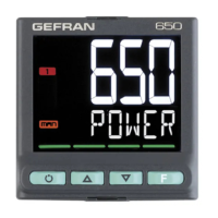
SERIES 650 / 1250 / 1350
650 1250 1350
ALARMS
Continuous
(C)
Number: 1 max
Current: 4...20mA
R
out
< 500 Ω
Resolution: 12 bit
Isolated from main input
Analog retransmission
(A1)
Number: 1 max
Signal: 10V, 0/4...20mA
0...10 V, max 20 mA, R
out
: > 500 Ω
0...20 mA, 4...20 mA, R
out
: < 500 Ω
Resolution: 12 bit
Isolated from main input
Number of alarm functions 4 max, assignable to an output
Possible configurations
Maximum, minimum, symmetric, absolute/relative, exclusion at firing, memory, reset from keypad and/or contact,
LBA, HB,
HBB Hold Back Band if enabled with Programmer function
CONTROL FUNCTIONS
CONTROL
Type Single loop
Control PID, ON/OFF, single action heat or cool, double action heat/cool
Control output
Continuous or ON/OFF
Cycle time: constant or optimized (BF)
Control output for motorized
valves
OPEN/CLOSE for floating motorized valve on Relay, Solid-state, Triac outputs
SETPOINT
PROGRAMMER
Number of programs
Max 4, Start / Stop / Reset / Skip via digital inputs and/or outputs from logic operations
Output state: Run /Hold / Ready / End
Number of steps
Max 12, each with own setpoint, ramp time and hold time; Times settable in HH:MM or MM:SS
Max 4 consents, configurable for ramp and for hold
Max 4 events, configurable in ramp and in hold
MULTIPLE
SETPOINTS
Number of
setpoint
Max 4, selectable from digital input
Each setpoint change is subject to set ramp, different for up and down ramp
LOGIC
1
OPERATIONS
Function blocks
Max 16, with 4 input variables per block. The result can act on the state of the controller, of the programmer on alarms
and outputs. Each function contains an incorporated timer block timer.
TIMER
FUNCTION
Modes
START / STOP
STABILIZATION (timer is on when PV enters a band set around setpoint; at end of count you can activate an
output, shut down SW or change SP1/SP2) FIRING (timed activation of control after power on)
ENERGY
COUNTER
Calculation done on nominal line voltage and nominal load power or on rms current measured on load via CT
DIAGNOSTIC
Short circuit or open circuit (LBA alarm)
Interrupted or partially interrupted load (HB alarm)
Short circuit of control output (SSR alarm)
RETENTIVE
MEMORY
Type EEPROM
Max. number of writes 1.000.000
SERIAL INTERFACE
Type: RS485
Baudrate: 1200, 2400, 4800, 9600, 19.200, 38.400, 57.600, 115.200 bit/s
Protocoll: MODBUS RTU
Isolated from main input
GENERAL DATA
POWER SUPPLY
Operating voltage
100...240 VAC/VDC ±10%, 50/60 Hz
(on request 20...27 VAC/VDC ±10%)
Power dissipation 5 W max 10 W max 10 W max
Protections Overvoltage 300 V / 35 V
Connection Screw terminals and crimp connector, max. wire section 1 mm
2
CONNECTIONS
Serial configuration port
(for USB connection)
Connector: microUSB
Inputs and outputs Screw terminals and crimp connector, max. wire section 2,5 mm
2
AMBIENT
CONDITIONS
Use Indoor
Altitude 2000 m max
Operating temperature -10 ... +55 °C (as per IEC 68-2-14)
Storage temperature -20 ... +70 °C (as per IEC 68-2-14)
Relative humidity 20...85% RH non-condensing (as per IEC 68-2-3)
PROTECTION
LEVEL
IP 65 on front panel (as per IEC 68-2-3)
ASSEMBLY
Positioning On panel, removable faceplate
Installation regulations
Installation category: II; Pollution degree: 2,
Isolation: double
DIMENSIONS
48X48 mm (1/16 DIN), Depth.: 80 mm 48X96 mm (1/8 DIN) Depth.: 80 mm 96X96 mm (1/4 DIN) Depth.: 80 mm
WEIGHT
0,16 kg 0,24 kg 0,24 kg
CE STANDARDS
EMC
(electromagnetic
compatibility)
EMC p(electromagnetic compatibility): conforms to directiv 2014/30/EU with reference to standard EN 61326-1
emission in industrial environment class A for models 650 LV
emission in residential environment class B for models 650 HV
Safety LVD: conforms to directiv 2014/35/EU with reference to standard EN61010-1
UL Conformity C/UL/US File no. E216851
EAC Conformity TC N° RUД-IT.AЛ32.b.01762
FM FM approvals project NO: 0003054712

 Loading...