Battery
8A
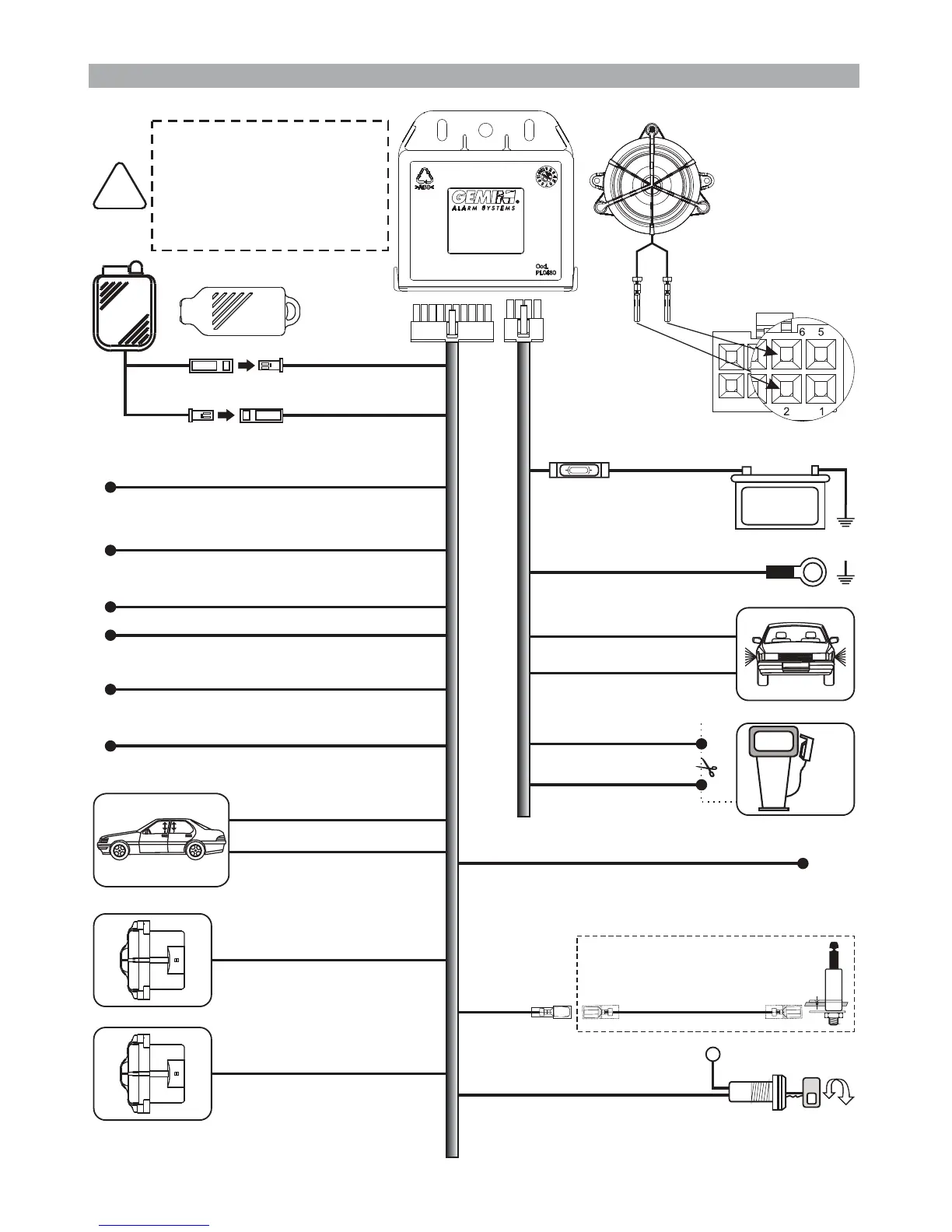
MAX !
BLACK marked “M”
GROUND
POSITIVE
BLACK marked “R”
WHITE-ORANGE
ORANGE
ORANGE
Input for system operation
via the turn indicators
Turn indicators output
BLACK marked “G”
+30
Ignition
BLACK marked “H”
BLACK marked “H”
Engine immobilizaton
External sensors input
Door trigger positive/negative input
Comfort output (negative)
Positive output with system armed (+A)
GREEN-BLACK
GREEN-BROWN
WHITE-BLACK
PINK
ELECTRONIC KEY
Connection
of 933 unit
with supplied
siren
Before carrying out
electrical connections,
disconnect the negative
battery terminal.
Re-connect ONLY after
completion.
!
Red
Black
Green
Brown
1
567
234
8
YELLOW-BLUE
GREEN-BLUE
YELLO -BLACKW
Additional siren or
vehicle horn
(negative output
during alarm)
BLUE
CAN BUS signal
LIGHT BLUE (CAN-L)
LIGHT BLUE-GREY (CAN-H)
Self-powered siren output
(art. 7725, lack of negative
during alarm) or
Hazard warning lights
Input for system operation
via door lock motor unit
OPTIONAL
GREEN
Bonnet switch

 Loading...


