5.0 - CONNECTORS TABLES
-1-
-2-
-3-
-4-
-5-
-6-
-7-
-8-
-9-
-10-
-11-
-12-
-13-
-14-
-15-
-16-
-17-
-18-
-19-
-20-
-----
YELLOW-BLUE
GREEN-BLUE
-----
GREEN-BROWN
GREEN
BROWN
BLACK
RED
BLACK marked “G”
LIGHT BLUE-GREY
LIGHT BLUE
PINK
GREEN-BLACK
GREEN
BLUE
WHITE-BLACK
YELLOW-BLACK
-----
WHITE-ORANGE
WIRE FUNCTIONPOSITION
WIRE COLOUR
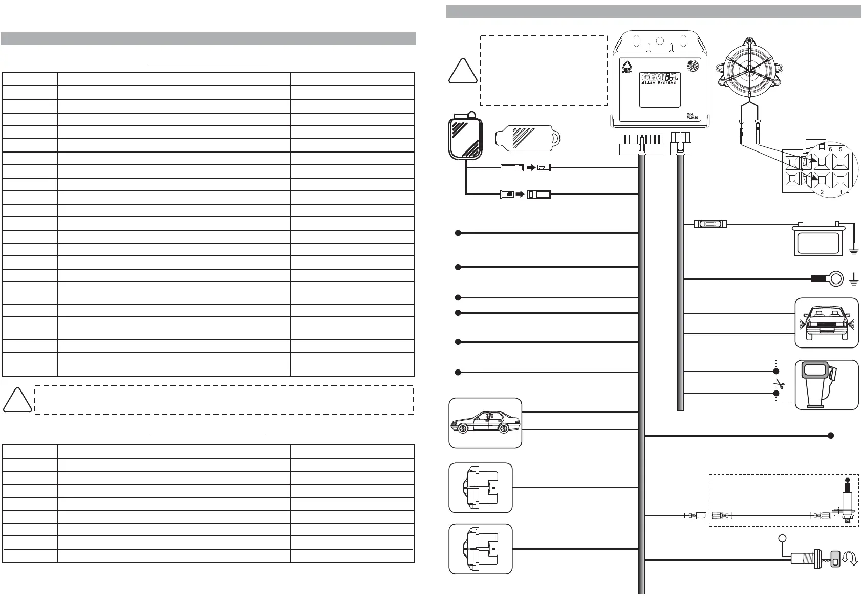
6.0 - COMPLETE ELECTRIC DIAGRAM
5.1 - 20-WAY CONNECTOR
INSTALLER MANUAL
WHITE-ORANGE wire must ALWAYS be connected if system is to operate through the
turn indicators.
!
-----
Signal for system arming
Signal for system disarming
-----
Doors push-button positive/negative input
Receptacle for electronic key input
Receptacle for electronic key negative ground
LED negative output
LED positive output
Positive under key
CAN BUS signal (CAN-H)
CAN BUS signal (CAN-L)
Positive output with system armed (+A)
External sensors negative input
Bonnet push-button negative input
Self-powered siren (lack of negative during alarm) or
impulse optic signalling
Comfort negative output
Supplementary siren or vehicle claxson output (negative
output during alarm)
-----
Input for self-learning and system arming/disarming by
turn indicators
PAGE 06 - INSTALLER MANUAL INSTALLER MANUAL - PAGE 07
Ground
Siren output
Positive
Turn signals positive output
Engine block
Siren output
Engine block
Turn signals positive output
-1-
-2-
-3-
-4-
-5-
-6-
-7-
-8-
BLACK marked “M”
-----
BLACK marked “R”
ORANGE
BLACK marked “H”
-----
BLACK marked “H”
ORANGE
WIRE FUNCTIONPOSITION
WIRE COLOUR
5.2 - 8-WAY CONNECTOR
15A
+
Battery
8A
MAX !
BLACK marked “M”
GROUND
POSITIVE
BLACK marked “R”
WHITE-ORANGE
ORANGE
ORANGE
Input for system operating
through vehicle turn indicators
Turn signals indicators
BLACK marked “G”
+30
Positive under key
BLACK marked “H”
BLACK marked “H”
Engine block
External sensors input
Doors push-button positive/negative input
Comfort output (negative)
Positive output with system armed (+A)
GREEN-BLACK
GREEN-BROWN
WHITE-BLACK
PINK
ELECTRONIC KEY
Connection
of 933 unit
with supplied
siren
Before carrying out all
electrical connections,
disconnect the negative
battery terminal and re-
connect again after
completion.
!
Red
Black
Green
Brown
1
567
234
8
YELLOW-BLUE
GREEN-BLUE
YELLO -BLACKW
Supplementary siren or
vehicle horns
(negative output
during alarm)
BLUE
CAN BUS signal
LIGHT BLUE (CAN-L)
LIGHT BLUE-GREY (CAN-H)
Self-powered siren output
(art. 7725, negative
during alarm
lack of
) or impulse
optical signals
Input for system operating
through vehicle door
lock motor unit
OPTIONAL
GREEN
Bonnet switch

 Loading...


