7.0-C
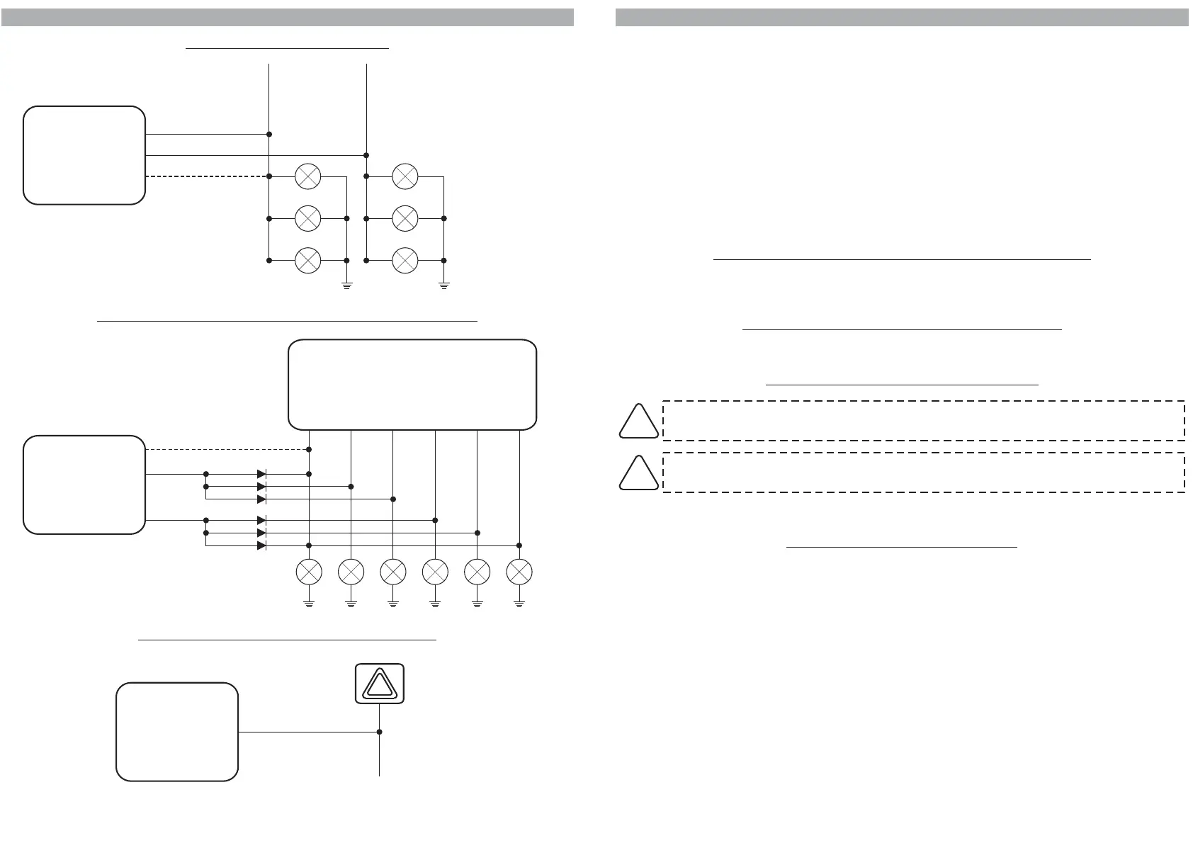
7.1 - STANDARD CONNECTIONS
ONNECTION FOR TURN SIGNALS ACTIVATION
8.0 - SELECTION OF CONNECTIONS TO ARM/DISARM THE SYSTEM
!
!
!
!
!
CAN-BUS line.
.
.
.
CAN-BUS line.
System arming/disarming and alarm are managed through CAN-BUS line.
(see available
diagrams at web-site www.gemini-alarm.com).
8.1 - CONNECTIONS AND MANAGEMENT BY CAN-BUS LINE
8.2 -
8.3 - CONNECTIONS TO TURN INDICATORS
The 933 system can operate in various modes according to the vehicle on which it is installed and
depending on the connections that can be made.
The CAN-BUS mode offers yet another operating solution.
It enables the system to be managed through the CAN-BUS line and operate in combination with the
CAN signals, with the turn indicators flashes and/or the door lock motor unit.
The system automatically manages the different arming/disarming signals.
Consult the tecnical installation charts for the available connections for each vehicle.
The various arming modes are listed below and the connections indicated in the following paragraphs.
Arming through
Arming through door lock motor unit
Arming through self-learning of turn indicators flashes
Arming through turn indicators flashes and door lock motor unit
Arming through turn indicators flashes, door lock motor unit and
Therefore only connect the alarm system CAN BUS line to the vehicle CAN line wires
System arming/disarming connections must be made to the vehicle door lock motor unit (polarity
inversion).
CONNECTIONS TO DOOR LOCK MOTOR UNIT
If turn indicators flashes are identical on locking and unlocking, connect the door lock
motor unit.
If the turn indicators flash when unlocking with the car mechanical key, do not make this
connection.
!
!
To armi/disarm the system, connect the WHITE-ORANGE wire to a wire of the turn indicators.
8.4 - “MIXED” CONNECTION OPTION
This type of connection allows the system to operate through the CAN BUS line with the turn indicators
or the door lock motor unit or both.
The system automatically manages the different lock/unlock signals according to the programming
and the connections made.
PAGE 08 - INSTALLER MANUAL INSTALLER MANUAL - PAGE 09
GEMINI 933
SYSTEM
GEMINI 933
SYSTEM
GEMINI 933
SYSTEM
RIGHT TURN
INDICATORS
LEFT TURN
INDICATORS
ORANGE
WHITE-ORANGE
ORANGE
TURN INDICATORS
CONTROL UNIT
ORANGE
WHITE-ORANGE
ORANGE
7.2 - CONNECTIONS FOR VEHICLES WITH SEPARATE LINES
7.3 - CONNECTION TO HAZARD PUSH-BUTTON
VEHICLE
ELECTRICAL
EQUIPMENT
BLUE
WHITE-ORANGE wire must ONLY be
connected if the system is to operate
through turn indicators.
WHITE-ORANGE wire must ONLY be
connected if the system is to operate
through turn indicators.
Insert nr. 6
2 Ampere
diodes.
Select “optical pulse signals”
in the “SYSTEM
PROGRAMMING” menu.
Do not make this connection
if the system is to operate
through turn indicators.
Front
LH
Rear
RH
Side
LH
Side
RH
Rear
LH
Front
RH

 Loading...


