1.0
2.0
3.0
4.0
5.0
7.0
11.0
12
13.0
14.0
15.0
- INTRODUCTORY NOTE............................................................................................
- REMOTE CONTROL 738W AND BATTERY REPLACEMENT..................................
- OPERATING INSTRUCTIONS...................................................................................
3.1 - Complete system arming..........................................................................................
3.2 - System arming with sensors exclusion.....................................................................
3.3 - Passive arming.........................................................................................................
3.4 - Arming delay.............................................................................................................
3.5 - System armed..........................................................................................................
3.6 - Alarm, inhibit time between alarms and alarm cycles...............................................
3.7 - System disarming.....................................................................................................
3.8 - Alarm memory...........................................................................................................
- PINOUT TABLES........................................................................................................
- WIRING DIAGRAM.....................................................................................................
- CONNECTIONS TO ARM/DISARM THE SYSTEM....................................................
.................................................
...............................................................
....................................
..........................................................................................
......................................................
8.3 - Passive arming.........................................................................................................
8.4 - Door switch polarity selection...................................................................................
ouble pulse unlock.................................................................................................
...............................................
...............................................................
- DELETING PROGRAMMED DEVICES....................................................................
..................................................
.....................................................................
................................................................................
- SYSTEM RESET......................................................................................................
- TECHNICAL SPECIFICATIONS...............................................................................
- WASTE ELECTRICAL AND ELECTRONIC EQUIPMENT DIRECTIVE
(WEEE).....................................................................................................................
USER MANUAL
INSTALLER MANUAL
6.0
8.0
9.0
10.0
.0
- VEHICLE CODE PROGRAMMING............................................................................
7.1 - Operation via CAN-BUS line...................................
7.2 - Operation via remote control.....................
- SYSTEM PROGRAMMING....................................................
8.1 - Optical signals................
8.2 - Acoustic signals..................................................
8.5-D
- SYSTEM PROGRAMMING EXAMPLE.......................
- LEARNING NEW DEVICES......................
- ULTRASONIC VOLUMETRIC PROTECTION........
12.1 - Connections and positioning.............
12.2 - Sensor adjustment..................
PAGE 02
1.0 - INTRODUCTORY NOTE
Dear customer, thank you for choosing this GEMINI product designed and manufactured in Italy
specifically for recreational vehicles.
This new generation 93 MHW CAN BUS alarm system has been implemented with a 2.45GHz
transceiver and ZigBee wireless technology with anti-jamming reliability.
Please read the present manual carefully to familiarize yourself fully with the operation of your alarm
system and do keep it for future reference.
The following signs are used throughout the manual to emphasize important instructions or special
information:
3
PAGE 03
UK
TABLE OF CONTENTS
For the installer.
This sign indicates that the system will operate according to the selected connections
and programming or it simply provides useful setup instructions.
!
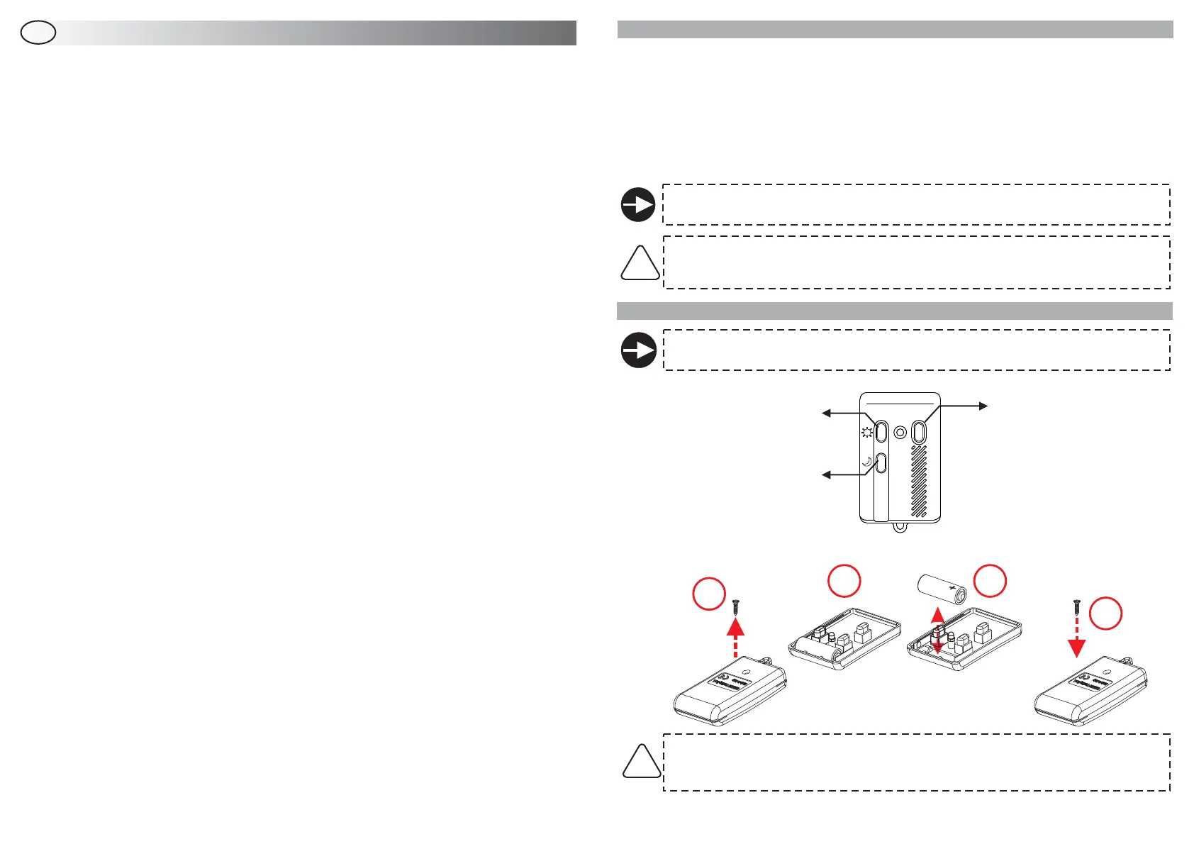
2.0 - REMOTE CONTROL 738W AND BATTERY REPLACEMENT
If the right connections have been made, the vehicle doors will lock/unlock when pressing
the arming/disarming buttons.
BUTTON 1:
TOTAL SYSTEM ARMING
(and door lock)
BUTTON 3:
PARTIAL ARMING
(door lock + sensor exclusion)
BUTTON 2:
SYSTEM DISARMING
(and door unlock)
4
4
1
1
2
2
3
3
Use only 23AE batteries.
Discard used batteries properly in special dedicated containers.
ATTENTION: Risk of explosion if battery is replaced by an incorrect type.
If the LED blinks 3 times at the press of a button, the battery is weak and must be replaced as follows:
ON
OFF
For the user.
This sign highlights useful information.
PAGE 03
PAGE 03
PAGE 04
PAGE 04
PAGE 04
PAGE 04
PAGE 04
PAGE 04
PAGE 05
PAGE 05
PAGE 05
PAGE 06
PAGE 07
PAGE 08
PAGE 09
PAGE 13
PAGE 14
PAGE 14
PAGE 14
PAGE 14
PAGE 15
PAGE 09
PAGE 09
PAGE 09
PAGE 10
PAGE 10
PAGE 10
PAGE 10
PAGE 10
PAGE 10
PAGE 11
PAGE 12
!
 Loading...


