INTRODUCTION
A typical brushless type portable generator will need
4 major components to function—a prime mover, a
stator, a rotor, and a capacitor.
As the engine starts to crank, residual magnetism
from the rotor creates magnetic lines of flux. The
lines begin to cut the excitation winding and induce
a small voltage into the winding. The voltage causes
the capacitor to charge. When the capacitor has fully
charged it will discharge a voltage that will be induced
back into the rotor. The AC voltage induced into the
rotor is rectified using a diode. The magnetic lines of
flux from the rotor will increase, causing output volt-
age to increase. The charge and discharge relation-
ship that the capacitor and rotor share is the voltage
regulation system that allows the generator to main-
tain 240 volts.
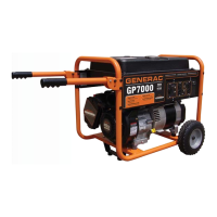
Figure 1 shows the major components of a typical GP
Series brushless AC generator.
STATOR
ROTOR
ENGINE
CAPACITOR
Figure 1. AC Generator Exploded View
STATOR ASSEMBLY
The stator has three windings wound separately
inside the can. Two are the power windings and are
located on Wire 44 (Hot) and Wire 33 (Neutral), the
other winding is located on Wire 11 (Hot) and Wire 22
(Neutral). The third winding is called the DPE winding
or Displaced Phase Excitation winding and is located
on Wire 2 and Wire 6.
ROTOR ASSEMBLY
The 2-pole rotor must be operated at 3600 rpm to
supply a 60 Hertz AC frequency. The term “2-pole”
means the rotor has a single north magnetic pole and
a single south magnetic pole. It spins freely inside
the stator can and is excited by the charging and dis-
charging of the capacitor. It has two diodes that rec-
tify voltage induced from the Excitation winding to DC
voltage. The rotor bearing is pressed onto the end of
the rotor shaft. The tapered rotor shaft is mounted to
a tapered crankshaft and is held in place with a single
through bolt.
Note: Some Rotors have a magnet placed inside
to help excite the rotor after it has been left idle
for a long period of time.
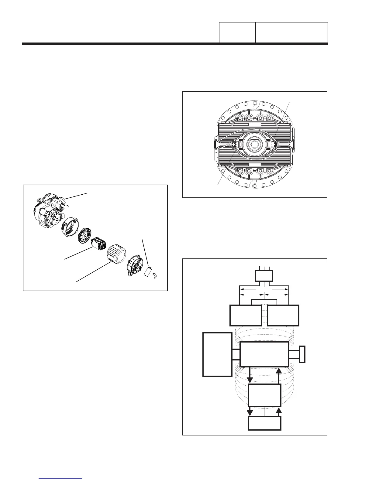
DIODE B
COIL 2
COIL 1
DIODE A
Figure 2. Rotor and Diodes
CIRCUIT BREAKERS
Each individual circuit on the generator is protected
by a circuit breaker to prevent overload.
CAPACITOR
STATOR
EXCITATION
WINDING
STATOR
POWER
WINDING
STATOR
POWER
WINDING
MAGNETIC
FIELD
MAGNETIC
FIELD
MLB = MAIN LINE
CIRCUIT BREAKER
ROTOR
TO LOAD
MLB
ENGINE -
DIRECT
DRIVE
AUTOMATIC
VOLTAGE
REGULATOR
+-
STATOR
EXCITATION
WINDING
STATOR
POWER
WINDING
STATOR
POWER
WINDING
MAGNETIC
FIELD
MAGNETIC
FIELD
SENSING
MLB = MAIN LINE
CIRCUIT BREAKER
ROTOR
TO LOAD
MLB
ENGINE -
DIRECT
DRIVE
120 VAC 120 VAC
240 VAC
120 VAC 120 VAC
240 VAC
A B
CAPACITIVE DISCHARGE DIRECT EXCITATION
Figure 3. Generator Operating Diagram
PART 1
GENERAL INFORMATION
SECTION 1.3
BRUSHLESS, CAPACITOR EXCITATION SYSTEM
Page 16

 Loading...