Page 42
TEST 20 – CHECK 1.5 AMP FUSE
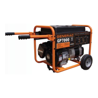
Figure 1. A Typical 1.5 Amp Fuse
DISCUSSION:
The fuse protects the wiring and the battery charger
from a short circuit.
PROCEDURE:
Push in on fuse holder cap and turn counterclockwise.
Then, remove the cap with fuse. Inspect the fuse.
RESULTS:
If the fuse element has melted open, replace the fuse
with an identical size fuse. If fuse is good, refer back
to flow chart.
TEST 21 – CHECK BATTERY & CABLES
PROCEDURE:
Inspect the battery cables and battery posts or termi-
nals for corrosion or tightness. Measure the voltage at
the terminal of the Starter Contactor and verify 11-12
volts DC is available to the generator during cranking.
If voltage is below 11 volts DC, measure at the battery
terminals during cranking. If battery voltage is below
11 volts DC, recharge/replace battery. If battery or
cables are still suspected, connect an alternate bat-
tery and cables to the generator and retest.
RESULTS:
1. Clean battery posts and cables as necessary. Make sure
battery cables are tight.
2. Recharge the battery, if necessary.
3. Replace the battery, if necessary.
4. If battery is good, but engine will not crank, refer back to
Flow Charts.
TEST 22 – CHECK VOLTAGE AT STARTER
CONTACTOR (SC)
PROCEDURE:
1. Set voltmeter to measure DC voltage.
2. Disconnect Wire 16 from the Starter Contactor located
on the Starter motor.
3. Connect the positive meter test lead to Wire 16 previ-
ously removed. Connect the negative meter test lead to
frame Ground.
4. Place the START-RUN-STOP Switch to START. 12 VDC
should be measured.
5. Reconnect Wire 16 to the Starter Motor.
RESULTS:
Refer back to flow chart.
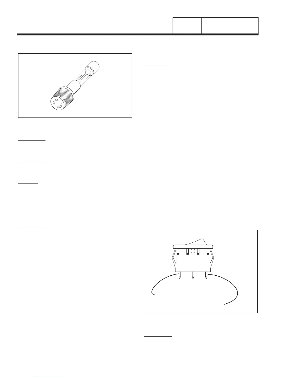
TEST 23 – CHECK START-RUN-STOP SWITCH
DISCUSSION:
The START-RUN-STOP switch utilizes ground potential
to start and shutdown the engine. When the switch is
actuated to the START position a ground is applied to
the starter contactor where positive 12VDC is already
available allowing the engine to crank. Once the ground
is removed by putting the switch in the RUN posi-
tion it disengages the starter allowing the engine to
operate normally. When the switch is actuated to the
STOP position a ground is applied to the magneto coils
grounding them out and inhibiting spark from occurring.
1A 1B1
WHT
STOP RUN START
0 GD 13A
TO MAGNETO
GROUND TO
STARTER CONTACTOR
Figure 2. START-RUN-STOP Switch
PROCEDURE:
1. Set a voltmeter to measure resistance.
2. Remove all wires from the START-RUN-STOP Switch
(SW1).
PART 3
DC CONTROL
SECTION 3.3
DIAGNOSTIC TESTS

 Loading...