6 Owner’s Manual for Portable Generator
Figure 2-2. Frame Foot Assemblies
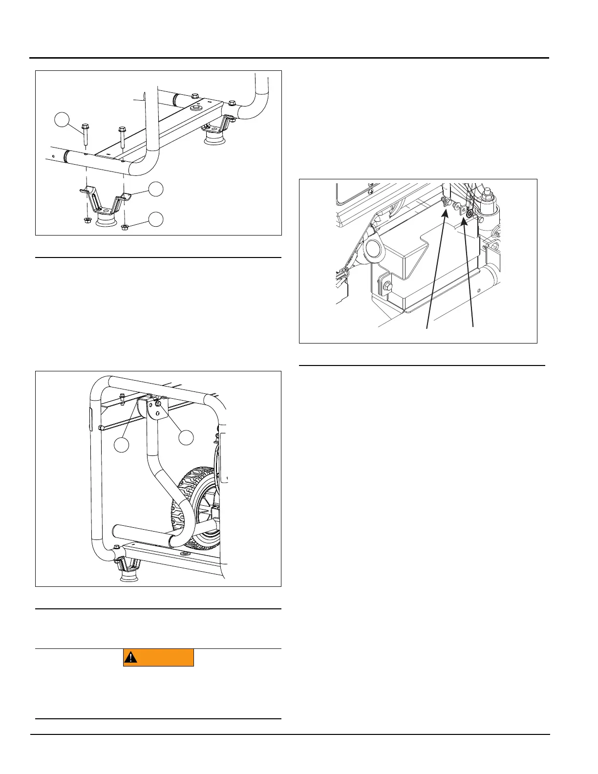
2.2.4 — Installing Handle
1. Insert handle into bracket 90 degrees counter-clock-
wise to avoid spring-loaded button interference.
Twist into place. (Figure 2-3).
2. Slide the M8 Bolt (F) through the handle bracket and
handle and install the M8 Nut (H). Tighten securely
using two 13mm wrenches.
Figure 2-3. Handle
2.2.5 — Battery Cables
NOTE: The battery shipped with the generator has
been fully charged. The positive and negative cables
are NOT connected and must be attached prior to
operation.
The NEGATIVE (black) (-) battery cable should:
1. Always be DISCONNECTED FIRST.
2. Always be CONNECTED LAST.
Use two 8 mm wrenches to tighten battery hardware.
Figure 2-4. Battery Connections
NOTE: A battery may lose some of its charge when
not in use for prolonged periods of time. If the bat-
tery is unable to crank the engine, plug in the 12V
charger included in the accessory box. RUNNING
THE GENERATOR DOES NOT CHARGE THE BAT-
TERY.
2.3 — Emissions Information
Locate the emissions compliance decal on the engine to
determine what standards the generator meets, and to
determine which warranty applies. This generator is certi-
fied to operate on gasoline. The emission control system
includes the following components (if equipped):
• Air Induction System
— Intake Pipe / Manifold
— Air Cleaner
•Fuel System
— Carburetor/Mixer Assembly
— Fuel Regulator
• Ignition System
— Spark Plug
— Ignition Module
• Exhaust System
— Exhaust Manifold
— Muffler
— Pulsed Air Valve
— Catalyst
(000130)
WARNING
Accidental Start-up. Disconnect the negative battery
cable, then the positive battery cable when working
on unit. Failure to do so could result in death or serious
injury.

 Loading...