Owner’s Manual for Portable Generator 7
3.1 — Know The Generator
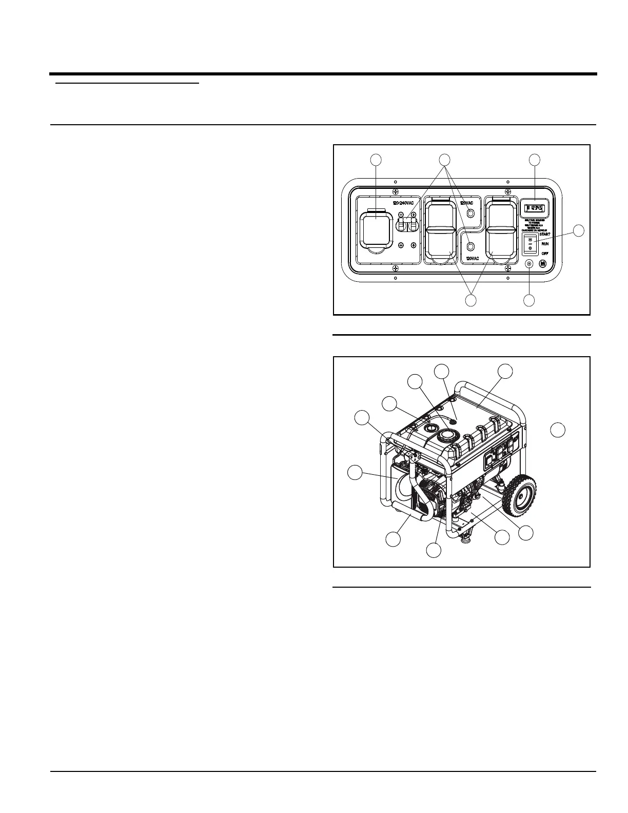
Compare the generator to Figure 3-1. through Figure 3-2.
to become familiarized with the locations of various con-
trols and adjustments.
Read the Owner’s Manual and Safety Rules before
operating this generator.
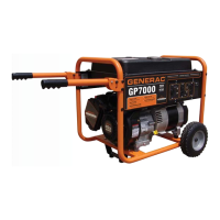
1. 120/240 Volt AC, 30 Amp, Locking Receptacle –
Supplies electrical power for the operation of 120
and/or 240 Volt AC, 30 Amp, single-phase, 60 Hz
electrical lighting, appliance, tool and motor loads.
2. Circuit Breakers (AC) – A 2-pole circuit breaker pro-
tects the rated output of the 30 Amp Twistlock outlet.
Each duplex receptacle provides a push-to-reset cir-
cuit breaker to protect against electrical overload.
3. Hour Meter - Tracks hours of operation to perform
required maintenance.
4. Battery Charger Input – Permits recharging of the
battery. A 12 volt charger is included. A 3 Amp in-line
fuse is located behind the control panel to protect the
battery when charging.
5. 120 Volt AC, 20 Amp Duplex Outlets – Supplies
electrical power for the operation of 120 Volt AC, 20
Amp, single-phase, 60 Hz, electrical lighting, appli-
ance, tool and motor loads.
6. Fuel Gauge - shows fuel level in tank.
7. Roll Over Valve - passes fuel vapors to the engine.
8. Battery - provides power for electric starter.
9. Oil Fill/Dipstick - check oil level and add oil here.
10. Oil Drain - drain plug for removing used oil from the
crankcase.
11. Handle – used to transport generator.
12. Recoil Starter - used to start engine manually.
13. Air Filter - filters air as it is drawn into the engine.
14. Fuel Cap - remove to fill fuel tank, replace when tank
is full.
15. Fuel Shut Off – valve between fuel tank and carbu-
retor.
16. Fuel Tank - holds fuel supply.
17. Muffler – quiets the engine (not shown).
18. Grounding Location - grounds the generator to an
approved earth ground here. See “Grounding the
Generator” for details.
19. Start/Run/Off Switch – controls the operation of the
generator.
Figure 3-1. Control Panel - CSA/49 State
Figure 3-2. Generator Controls
3.1.1 — Connection Plugs
3.1.1.1 — 120 VAC, 20 Amp, Duplex
Receptacle
This is a 120 Volt outlet protected against overload by a
20 Amp push-to-reset circuit breaker (Figure 3-3). Use
each socket to power a NEMA 5-15P or 5-20P, 120 Volt
AC, single phase, 60 Hz electrical loads requiring up to a
combined 2400 watts (2.4 kW) or 20 Amps of current.
Use only high quality, well-insulated, 3-wire grounded
cord sets rated for 125 Volts at 20 Amps (or greater).
Section 3 Operation

 Loading...