5-1
SECTION 5: CYLINDER HEAD AND VALVES
GENERAL INFORMATION
Compression testing information and procedures is described in Sec-
tion 1, under “Troubleshooting”.
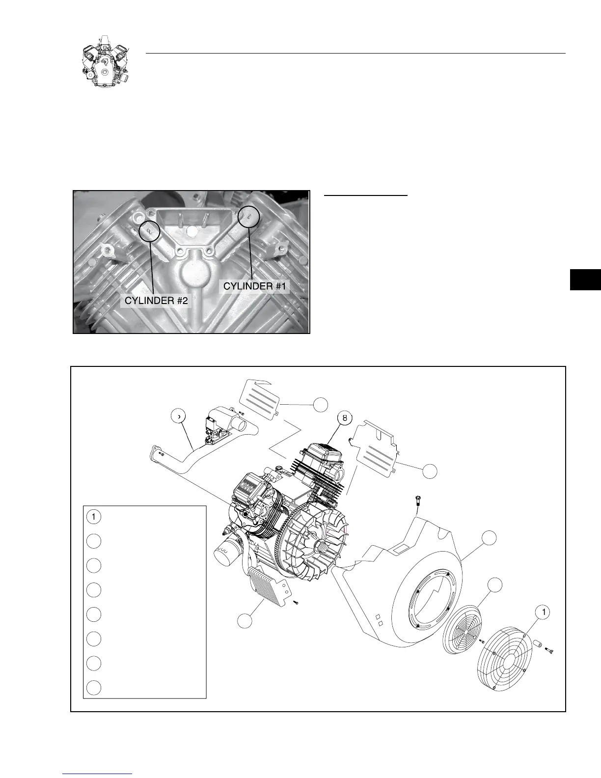
Cylinders are numbered as shown in Figure 5-1.
Note: Cylinder #1 is closest to the flywheel.
Figure 5-1.
REMOVE CYLINDER HEADS
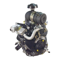
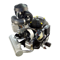
Remove exhaust system from engine. Disconnect choke and throttle
control cables. Remove spark plugs.
1. Remove the parts depicted in Figure 5-2.
a. Discard gaskets and valve cover seals.
REMOVE ROCKER ARMS:
1. Unlock jam nuts and remove two ball studs and rocker arm
assemblies (see Figure 5-3).
2. Remove push rods and identify each.
Note: Push rods develop a wear pattern. Mixing them from side to
side can increase this wear, leading to more frequent adjustments
and or loss of performance.
VALVE
VE
L
WER WRAPPE
PPER WRAPPE
BL
WER H
IN
IL
LE
INTAKE MANIF
LD
A
EMBL
R
TATIN
REE
FIN
ER
AR
Figure 5-2.
5
 Loading...